


195
Quick Start
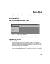
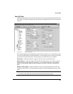
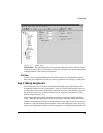
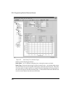
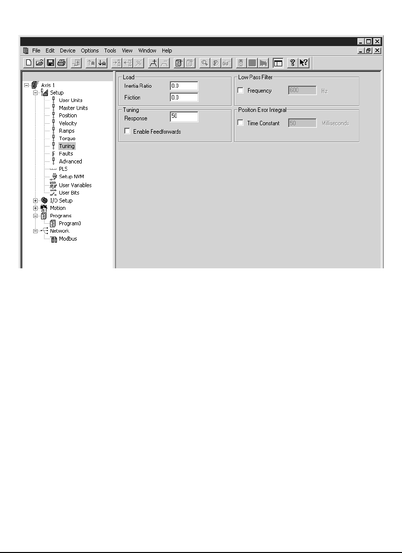
Figure 77: Tuning View
Inertia Ratio - This parameter is the ratio between the reflected inertia of the load and the
inertia of the motor rotor. For assistance in calculating the Inertia ratio, see the Determining
Tuning Parameter Values section of this manual.
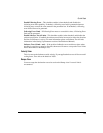
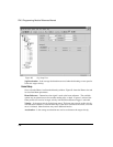
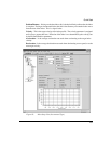
PLS View
Use this view to setup Programmable Limit Switches (PLS), if your application requires
them. They are assigned in the same way as the Assignments views in Step 3 of this guide.
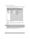
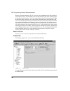
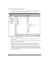
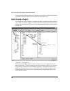
Step 3: Making Assignments
The Assignments view is found by expanding the I/O Setup group in the hierarchy. The
Assignments define how the system operates. Sources, located on the left side of the view,
are functions or events that activate based on drive/motor activity. Destinations, located on
the right side of the view, are functions that need to be triggered or activated (i.e. Index
Initiate, Program Initiate, etc.).
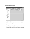
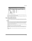
The example application requires initiating three indexes using three separate hardware
inputs. Therefore, the Input sources need to be assigned to the Index Initiate destinations.
To make an assignment, position your mouse pointer over the source you wish to assign to a
destination, click and hold the left mouse button. While still holding the button, drag your
pointer over the destination where you wish to assign this source, and release the button. The