2640A/2645A NetDAQ
Users Manual
6-28
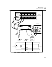
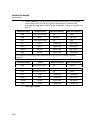
3. Verify Digital I/O Input for all Set Lines In sequence, individually ground
each DIO line to the GND line using the DIO wires connected in Step 1. Note
the change in the DIO status reported in the Spy window as follows:
None grounded Reported DIO Status = 255
DIO0 grounded Reported DIO Status = 254
DIO1 grounded Reported DIO Status = 253
DIO2 grounded Reported DIO Status = 251
DIO3 grounded Reported DIO Status = 247
DIO4 grounded Reported DIO Status = 239
DIO5 grounded Reported DIO Status = 223
DIO6 grounded Reported DIO Status = 191
DIO7 grounded Reported DIO Status = 127
4. Close Spy Window.
Totalizer Tests 6-27.
The Totalizer Tests check the Totalizer feature for counting and sensitivity.
Totalizer Count Test 6-28.
This test checks the ability of the Totalizer feature to count.
1. Enable Totalizer Debounce In NetDAQ Logger, select Setup | Instrument
Configuration to open the Instrument Configuration dialog box. Check
Totalizer Debounce if it is not already checked and click OK.
2. Open Spy Window Select the Spy command from the Utilities menu. Select
01TOTAL. Click OK to open the Spy window.
3. Increase Totalizer Count Connect the ∑ (Totalizer) test lead to the GND
line and disconnect again. Each time this is done, the Totalizer count should
increase one.
4. Verify Totalizer Count The Spy window displays the new Totalizer count
which is equal to the number of contacts between totalizer and ground.
5. Close Spy Window.
Totalizer Sensitivity Test 6-29.
This test checks the ability of the Totalizer feature to count voltage transition at a
particular sensitivity level.
1. Disable Totalizer Debounce In NetDAQ Logger, select Setup | Instrument
Configuration to open the Instrument Configuration dialog box. Uncheck
Totalizer Debounce if it is currently checked and click OK.


