Overview
Instrument Features and Capabilities
1
1-9
overflows (reaching the maximum count), the display briefly shows OL
(overload) and begins counting from zero again
A totalizer input from contact closures increments on the “open” portion of the
switch sequence close-open. To prevent switch contact “bounce” from triggering
false readings, select the Totalizer Debounce feature. A totalizer input from
voltage transitions increments during low-to-high voltage transitions with a
nominal threshold of +1.4 volts. The maximum voltage input is +30V dc, and the
minimum voltage input is -4.0V dc. The maximum totalizer rate is 5,000
transitions per second without debounce and 500 transitions per second with
debounce.
The instrument reports Totalizer status with scan data and can display it at the
front panel. You can clear the Totalizer count by cycling power to the instrument
or via NetDAQ Logger.
Trigger Input 1-11.
Trigger Input is an instrument connection used to trigger scans from an external
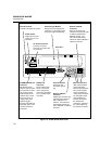
source. The connection uses the ALARM/TRIGGER I/O terminals TI and GND
(Figure 1-4). A contact closure or logic low between TI and GND triggers an
instrument scan if External Trigger is enabled. While the trigger input line is held
low, the instrument continues to scan at Interval 2.
When there is no trigger input, an internal pull-up resistor holds the input at logic
high (nominal +5.0V dc).
Trigger Output 1-12.
Trigger Output is an output line that, when enabled, goes to logic low for 125 µs
every time a scan begins. The connection uses the ALARM/TRIGGER I/O
terminals TO and GND (Figure 1-4). Use the Trigger Output to trigger other
instruments by their Trigger Input connection and to interface with external
equipment. An internal pull-up resistor holds the trigger output line at a logic high
(nominal +5.0V dc) when there is no trigger output.


