2640A/2645A NetDAQ
Users Manual
2-12
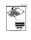
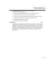
2. Loosen the wire clamp screw for the associated terminal.
3. Feed the wire into the gap between the connector body and the wire clamp.
4. Tighten the wire clamp; do not overtighten and crush the wire.
5. Repeat steps 2 through 4 for each wire.
6. Insert the connector in the rear panel.
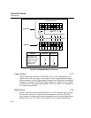
DIGITAL I/O
01234567
0
1
2
3
4
I/O Line 0
I/O Line 1
I/O Line 2
I/O Line 3
I/O Line 4
5
6
7
Σ
I/O Line 5
I/O Line 6
I/O Line 7
Totalizer Input
Signal Ground
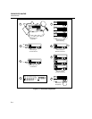
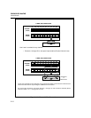
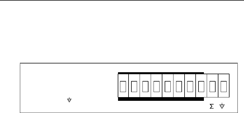
Figure 2-5. DIGITAL I/O Connector
Digital I/O 2-13.
The Digital I/O lines use terminals 0 to 7 and GND. You can use these lines either
as signal inputs or as alarm outputs. See Table A-3 in Appendix A for complete
specifications.
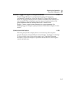
Totalizer 2-14.
The Totalizer uses terminals Σ and GND. The Totalizer counts contact closures or
voltage transitions with a maximum count of 4,294,967,295. See Table A-7 in
Appendix A for complete specifications.
Alarm/Trigger I/O Connections 2-15.
PCaution
To avoid damage to the instrument, do not apply any
voltages greater than 30V maximum between the
ALARM/TRIGGER I/O connector terminals and earth
ground.
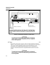
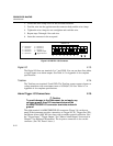
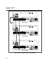
The eight-terminal ALARM/TRIGGER I/O connector (Figure 2-6) on the rear
panel of the instrument provides connections to Trigger In (TI), Trigger Out (TO),
and Master Alarm (MA) I/O lines along with a common ground connection. (See
the "Trigger Input," "Trigger Output," and "Master Alarm Output" discussions in
Chapter 1 for additional information.) The dc power connection is also on this
connector. (See "DC Power" above.).


