6 Maintaining and Troubleshooting the Gateway ALR 9200 Server
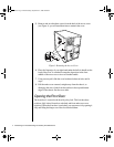
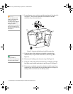
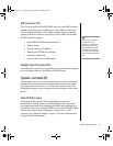
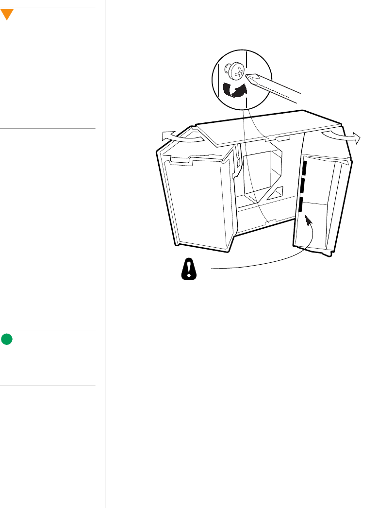
8. Loosen the two screws on the top and bottom edges of the chassis (A
in Figure 2). These screws attach the front subchassis and the
electronics bay to the main chassis.
Figure 2: Opening the Subchassis and Electronics Bay
9. Using the edges of the subchassis as handles, rotate the front
subchassis left, away from the main chassis, until it stops (B in
Figure 2).
10. Disconnect all cabling to the electronics bay (D in Figure 2).
11. Using the vertical edge of the electronics bay as a handle, rotate the
bay right, away from the main chassis, until it stops (C in Figure 2).
12. If necessary, completely remove the subchassis and electronics bay:
rotate the bays outward until the two pins that function as hinges for
the bays slide out of their slots. Set the bays aside.
Caution!
You must disconnect all
cabling to the electronics
bay before rotating/
removing the bay. Failure to
do so can result in serious
damage to system
components. The location of
the main connectors in the
electronics bay is marked as
D in Figure 2.
B
A
C
D
Note:
It may be easier to
disconnect the cables if you
remove the foam pad first.
3424.boo Page 6 Wednesday, September 2, 1998 9:23 AM


