


44 Maintaining and Troubleshooting the Gateway ALR 9200 Server
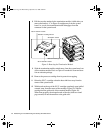
4. Push the ejector levers on the socket ends to the upright position.
5. Repeat steps two through four to install each DIMM.
6. Reinstall the memory module (see “Installing the Memory Module”
on page 44).
7. Reinstall the foam cover(s).
8. Reinstall the access cover using the original screws.
9. Connect all external cables and the power cords to the system.
10. Turn on the monitor and then the system.
11. Run the SSU (see “Resource Configuration Add-in Window” on
page 112) to configure the system and to properly attribute ECC
memory.
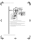
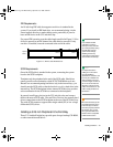
Installing the Memory Module
Once you have installed any DIMMs that you want, you must re-install the
memory module.
1. Observe the safety and ESD precautions in “Static Electricity
Precautions” on page 2.
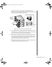
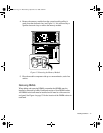
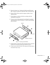
2. Holding the memory module by its edges, align the module so its edge
engages in the guide rail at the back of the electronics bay.
3. Push the memory module toward the system board until it fully
engages its connector.
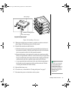
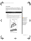
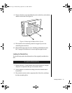
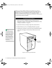
4. Install the foam pad in the electronics bay.
5. Replace the system access cover and screws.
To Install the Memory Module
Note:
DIMM slots on the memory
module must be installed
only in certain
configurations. See
“Memory Configuration” on
page 25 for requirements.
Caution!
The memory module is held
in place by the 242-pin
connector on the system
board, the guide rail at the
back of the electronics bay,
and a plastic guide at the
front of the electronics bay.
You must support the
module until it is fully seated
in the connector.
3424.boo Page 44 Wednesday, September 2, 1998 9:23 AM