


48 Maintaining and Troubleshooting the Gateway ALR 9200 Server
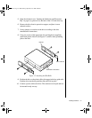
4. Attach the carrier to the drive with three screws of the appropriate size
and length (reuse the screws you removed before). Tighten the screws
firmly.
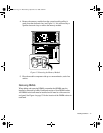
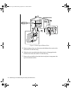
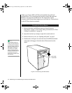
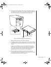
5. Position the carrier so that the two protruding notches fit into the
corresponding slits in the side of the 5.25-inch drive bay. Slide the
assembly toward the front of the system to engage the notches.
6. Make sure the front of the drive fits correctly in the front opening of
the system. When properly positioned, the carrier notches extend
slightly into the interior of the 5.25-inch drive bay and the threaded
hole in the carrier aligns with the threaded hole in the frame.
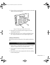
7. Secure the assembly to the 5.25-inch bay with the screw you removed
earlier; tighten the screw firmly.
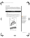
8. Connect the signal and power cables to the drive. The red stripe on the
signal cable must face toward the center of the drive.
9. Reinstall the foam pads, fans (see “Installing an Individual System
Fan” on page 62) and the access cover using the original screws.
10. Run the SSU or BIOS Setup to specify that the diskette drive is
installed in the system (“Modifying Resources” on page 114 or “Main
Menu” on page 85).
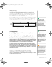
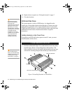
Drive Cabling Considerations
Excluding the diskette drive, there are two types of devices that can be
installed in the server; IDE devices and SCSI devices. This section covers
cabling consideration for both types of devices. These cable considerations
apply to any devices using the IDE or narrow SCSI controllers.
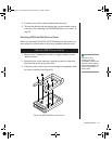
The number of devices you can install depends on:
• The number supported by the bus
• The number of physical drive bays available
• The combination of SCSI and IDE devices
Note:
The 3.5-inch diskette drive is
not installed in the 5.25-inch
drive bay. The diskette drive
carrier attaches to the
outside of the 5.25-inch
drive bay (see Figure 13 on
page 46).
3424.boo Page 48 Wednesday, September 2, 1998 9:23 AM