20 Maintaining and Troubleshooting the Gateway ALR 9200 Server
The keyboard controller is functionally compatible with the 8042A
microcontroller. The system can be locked automatically if no keyboard or
mouse activity occurs for a predefined length of time, if specified through
the SSU. Once the inactivity (lockout) timer has expired, the keyboard and
mouse do not respond until the previously stored password is entered.
USB External Connector (O)
One universal serial bus (USB) port provides connection for a growing list
of peripheral components including mouse, keyboard, joystick, monitor,
tape and diskette drives. Up to 127 devices can be daisy-chained from the
port. The USB port also provides hot-swap capability and dynamic resource
allocation for all peripherals attached to it with data transfer rates of up to
12 Mbps. USB drivers are provided as a part of most major operating
systems and should require no special procedures for implementation or
use.
Processors and Related Connectors
VRM Connectors (P, Q, R, S, T, U)
In this system each processor must have one VRM to adjust the voltage
supplied to the processor core and one to adjust the voltage supplied to the
second-level cache in the SEC cartridge. The first VRM is dedicated to a
single processor and provides the correct power to the processor core. The
second VRM provides power to the integrated second-level cache and can
support the cache on two SEC cartridges. Therefore each processor requires
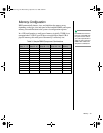
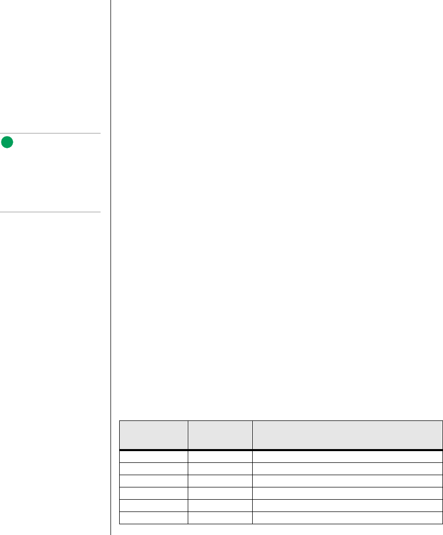
1.5 VRMs. See Table 2 for the allowed processor and VRM configurations.
Table 2: Processors and VRMs
Processor
Installed
VRM
Installed
VRM Function
Processor 1 VRM 1 Powers the processor core for processor 1
VRM 2 Powers the second-level cache for processors 1 and 2
Processor 2 VRM 3 Powers the processor core for processor 2
Processor 3 VRM 4 Powers the processor core for processor 3
VRM 5 Powers the second-level cache for processors 3 and 4
Processor 4 VRM 6 Powers the processor core for processor 4
Note:
A second USB port internal
to the system chassis is
provided at position FF as
shown in Figure 3 on
page 11
3424.boo Page 20 Wednesday, September 2, 1998 9:23 AM


