


40 Maintaining and Troubleshooting the Gateway ALR 9200 Server
Installing Hardware
The server includes expandability features that allow you to add several
types of hardware to the interior of the system. All of the procedures given
in this section use the ESD precautions identified in “Static Electricity
Precautions” on page 2. All of the procedures in this section refer to
Chapter 2, “Installing Components”.
Memory
Main memory resides on an add-in board, called a memory module. The
memory module contains slots for 16 DIMMs, each of which must be at
least 32 MB, and is attached to the system board through a 242-pin
connector. Memory amounts from 128 MB to 4 GB of DRAM are
supported, with a 64/72-bit four-way-interleaved pathway to main memory.
The 16 slots are divided into four banks of four slots each, labeled A
through D. These banks support 4:1 interleaving. The memory controller
supports EDO DIMMs only. The ECC used for the memory module is
capable of correcting single-bit errors (SBEs) and detecting 100 percent of
double-bit errors over one code word. Nibble error detection is also
provided.
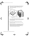
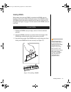
Removing the Memory Module
The memory module must be removed before you can change the memory
configuration. See “Memory” on page 23 for memory size and
requirements.
1. Observe the safety and ESD precautions in “Static Electricity
Precautions” on page 2.
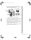
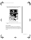
2. Remove the access cover (see “Opening the System” on page 3).
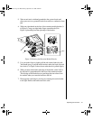
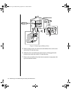
3. Remove the foam cover over the electronics bay.
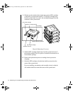
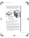
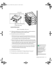
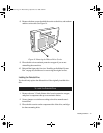
To Remove the Memory Module
3424.boo Page 40 Wednesday, September 2, 1998 9:23 AM