Installing Hardware 59
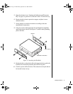
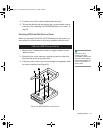
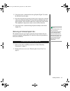
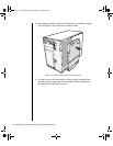
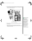
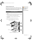
3. Using four screws, attach the fan to the grill plate (Figure 23) so that
the fan label faces the plate.
4. Insert the fan/grill plate assembly into the power supply bay so that the
cable points downward (Figure 23) from the fan toward the other two
power supplies, and so the fan’s label faces out the back of the chassis.
This alignment is important to ensure correct airflow direction.
5. Using four screws, attach the fan/grill plate assembly to the chassis
(Figure 23).
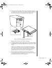
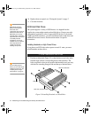
Removing an Individual System Fan
The subchassis houses up to eight system fans. Not all of these fans are
required in standard configurations. If a fan fails, follow this procedure to
remove the failed fan.
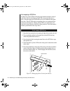
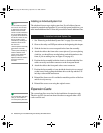
1. Observe the safety and ESD precautions in “Static Electricity
Precautions” on page 2.
2. Remove the access cover (see “Removing the Access Cover” on
page 3).
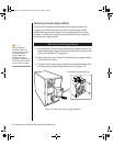
To Remove an Individual System Fan
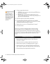
Note:
Correct airflow direction: The
side of each fan is
embossed with directional
arrows indicating airflow
direction. Always note the
direction of the arrows on a
fan before removing it. You
will need this information
later when you install a
different fan.
3424.boo Page 59 Wednesday, September 2, 1998 9:23 AM


