


26
Enhancements in Release F.05.05 through F.05.70
Enhancements in Release F.05.05 through F.05.60
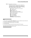
For example, suppose that the switch is in its default configuration (no multiple VLANs; GVRP
disabled, all ports untagged members of the default VLAN—VID = 1) with two optional gigabit
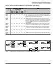
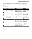
transceivers installed, and you wanted to use the switch ports as shown in table table 3, “Port Isolation
Plan”:
Table 3. Port Isolation Plan
Port Use Allowed Traffic Blocked
1 - 3 Local ports only for isolated work-
group access. (No network or
internet access.)
• Traffic between any ports in the
local set (ports 1, 2, and 3)
• Traffic between any port in the
local set and any port in the public
set (ports 10, 11, or 12)
Traffic between any port in
the local set and any port in
the private, group1, or
uplink port sets
4 - 8 Group1 ports for workgroup and
network/internet access
• Traffic between any ports in the
group1 set (ports 4 through 8)
• Traffic between any port in group1
and the uplink ports
Traffic between any port in
the group1 set (ports 4 - 8)
and any public, private, or
local ports
9 Private port to a secure end node; no
traffic exchange with non-uplink
ports on the switch.
Traffic between port 9 (private) and
the gigabit trunk used as an uplink
(ports 13 and 14).
Traffic between port 9 and
any port in the local, public,
or group1 port sets, or any
other private port on the
switch
10 - 12 Public ports for typical end-node
access.
• Traffic between any ports in the
public set (ports 10, 11, and 12)
• Traffic between any port in the
public set and any port in the local
or uplink port sets
Traffic between any port in
the public set (ports 10 - 12)
and any port in the group1
or private port sets
13 -14 Gigabit uplink to the network. • Traffic between any ports in the
uplink set (ports 13 and 14)
• Traffic between any port in the
uplink set and any port in the
public, private, or group1 sets
Traffic between any port in
the uplink set and any port
in the local set
1
2
3
4
5