


27
Enhancements in Release F.05.05 through F.05.70
Enhancements in Release F.05.05 through F.05.60
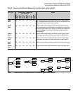
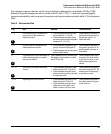
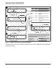
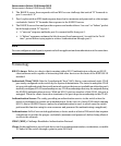
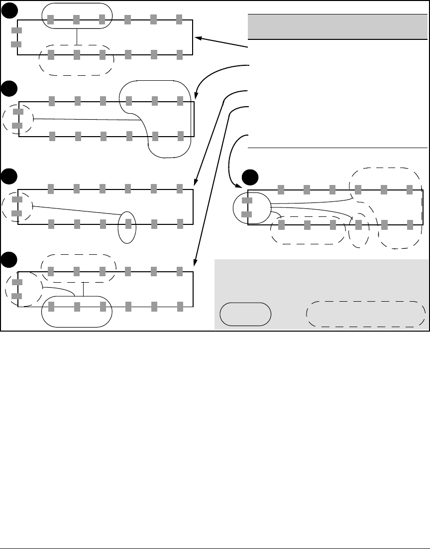
Figure 8. Example of Isolating Ports on a Series 2500 Switch
Assuming a switch in the factory-default configuration, you would configure the port isolation plan
in figure 8 as follows:
1 2 3 4 5 6
12 11 10 9 8 7
1 2 3 4 5 6
14
13
Port Mode Internal Traffic Destinations
Allowed by Port Isolation Mode
1 - 3 Local Each Other and Ports 10 - 12
4 - 8 Group1 Each Other and Ports 13 and 14
(uplinks)
9 Private Gigabit Trunk (ports 13 & 14)
10 - 12 Public Each Other, Ports 1 - 3, and the
Uplink Ports.
13 - 14 Uplink Ports 4 - 8 (group1), 9 (private), 10
-12 (public)
12 11 10 9 8 7
14
13
1 2 3 4 5 6
14
13
12 11 10 9 8 7
1 2 3 4 5 6
14
13
12 11 10 9 8 7
1 2 3 4 5 6
14
12 11 10 9 8 7
13
This figure illustrates the port isolation example described in table
3 on page 26. Each switch view belongs to the same configuration
and illustrates the indicated port set and the permitted
communication for that set.
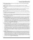
Configured
Port Set
Other Port Set(s) Available to a
Configured Port Set
2
1
3
4
5