


Optional Fibre Channel Card168
Connectors and Indicators
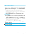
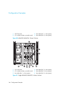
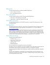
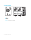
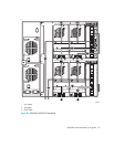
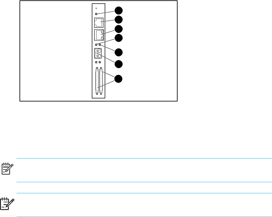
Figure 82 shows the connectors and indicators for the optional Fibre Channel board.
Figure 82 Connectors and indicators
NOTE: The Fibre Channel board serial cable is not the same as the library controller board serial
cable. The serial pinouts are different for each board, requiring different cables.
IMPORTANT: The Fibre Channel card can be reset by using a paper clip or other sturdy tool to
push the reset switch shown above the Power LED in Figure 82.
Power Indicator
The Fibre Channel card has one power LED X. LED definitions:
• Green - power has been applied
• Yellow - POST is in process or processor problems present
Serial Port
The Fibre Channel card has one serial port Y. The serial port can be used to access the
Serial/Telnet user interface, which is used to locally manage and configure the Fibre Channel card.
1 Power LED
2 Serial RJ-11 connector
3 Ethernet RJ-45 connector
4 Fibre Channel activity LED
5 Fibre Channel link LED
6 FC-LC connector
7 SCSI VHDCI connector (2)
Fibre
Channel
LVD/SE SCSl
0
1
EthernetSerial
Pwr.
Link/
Act
1
2
3
4
5
6
7
!