Chapter 3 - Connecting and Installing Your Impulse
3-8
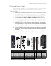
D. Connecting AC Power
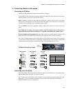
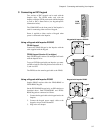
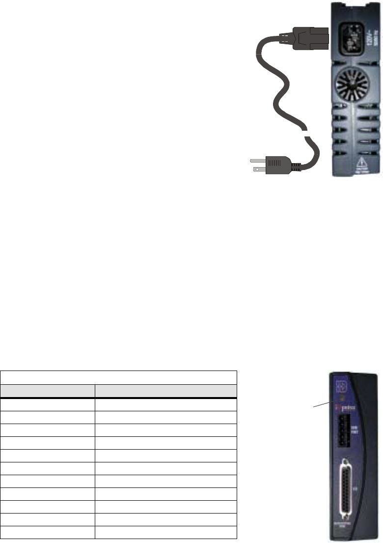
There is no ON/OFF switch on the Impulse. AC power is
applied by plugging the *power cord (included) into the
connector on top of the Impulse.
Input voltage must be in the range of 120 VAC ± 10%, single
phase, 50/60 Hz, 500 VA max @ 4 Amps. Operation outside
these specifications will result in reduced performance, drive
faults, and may damage the drive.
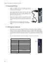
When power is applied, the LED on front of the drive should
briefly turn red, then steady green. If a red light is present, see
Section E of this chapter for more information on fault detection
codes.
*Note: If the AC power cord requires replacement, the
replacement must be rated for Hard Usage or Extra Hard
Usage.
E. LED Diagnostic Indications
The Impulse drive detects and resolves fault conditions (see table below). Faults are signaled by
either a steady red or a flashing red LED on the front panel. A solid green LED indicates normal
operation. A slowly flashing green LED indicates a shutdown (disabled), while a rapidly flashing
green LED signals a regen dump. Faults are cleared by either 1) cycling power, 2) sending a RESET
command via the serial port or configurable logic input, or 3) probing the motor if the LED is steady
red.
For more detailed explanation of faults refer to Chapter 7, Troubleshooting the Impulse.
To AC
Power
Supply
Diagnostic LED Indications
LED Signal Indication
Green (steady) Normal Operation
Slow Flashing Green Shutdown
Quick Flashing Green Regen Dump
Red (steady) Motor Not Probed
1 Flash Red Stalled
2 Flashes Red Undervoltage Fault
3 Flashes Red Overvoltage Fault
4 Flashes Red Overcurrent Fault
5 Flashes Red Interlock Fault
6 Flashes Red Overtemperature Fault
7 Flashes Red EEPROM Checksum Fault
LED


