Intel® Server Board Set SE8500HW4 Intel® Server Board Set SE8500HW4 Memory Board
Revision 1.0
Intel order number D22893-001
25
4.5.1.3 LEDs
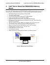
All LEDs are controlled by the BIOS through the Independent Memory Interface (IMI). Table 8
describes the LEDs on the Memory Board.
Table 8. Memory Board LEDs
Name Color Description
Mirror Green Memory Board is in a mirror mode
RAID Green Memory Board is in a RAID mode
Attention Amber When flashing, the Memory Board is in a hot plug event
Power
1
Green Memory Board is powered on, all rails are on
1B Amber DIMM_1B has had an error and needs to be replaced
1A Amber DIMM_1A has had an error and needs to be replaced
2B Amber DIMM_2B has had an error and needs to be replaced
2A Amber DIMM_2A has had an error and needs to be replaced
1- The power LED provides indication of Memory Board state. It is cleared when the Memory
Board is inactive and set when the Memory Board is included in the current memory
configuration. It blinks when a request is being serviced during a hot removal or hot add event.
4.5.2 Temperature Sensors and FRU
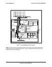
A dual temperature sensing device provides a sensor at the left and right of the DIMM sockets.
Server management sees this as one sensor, measuring the temperature drop across the board
which estimates the heat generated by the DIMMs.
An EEPROM device provides 256 bytes of programmable Field-Replaceable Unit (FRU) space.
Like all Intel server boards, this FRU is programmed during manufacturing to contain the board
version and serial number but may be programmed to meet integrator-specific needs.
4.5.3 I
2
C
The XMB, temperature sensor controller and FRU device are connected to the Mainboard
Baseboard Management Controller. The I
2
C bus addressing for these devices is slot dependant
and located on private I
2
C bus 3.
4.5.4 Independent Memory Interface (IMI)
The Independent Memory Interface (IMI) is simultaneous and bi-directional, with a read
bandwidth of up to 5.3 GB/s and a write bandwidth of up to 2.7 GB/s. The IMI also provides
support for Memory Board hot plug signals and protects all transfers with a combination of
packet-based CRC and/or x8 SDDC.
4.5.5 Serial Presence Detect (SPD)
The Serial Presence Detect (SPD) bus is a low frequency serial chain that is routed to each
DDR2 memory channel. The XMB acts as a master for the SPD bus and uses it to detect and
configure the DIMMs.


