Server Management Intel® Server Board Set SE8500HW4
Revision 1.0
Intel order number D22893-001
34
5.3 ACPI Power Control
The Intel
®
Server Board Set SE8500HW4 supports ACPI S0, S1 and S5 sleep states. When the
system is operating in ACPI mode, the operating system retains control of the powering on of
the system. During ACPI mode, operating system policy determines the entry methods and
wakeup sources for each sleep state. An ACPI-enabled operating system generates a System
Management Interrupt (SMI) to request that the system enables ACPI support. The BIOS
responds to the SMI by communicating to the BMC that ACPI support is required.
5.3.1 S1 Sleep State Support
During this state, the following events take place:
The front panel power LED blinks at a rate of 1 Hz with a 50% duty cycle.
The front panel reset button is protected by the BMC to prevent accidental system resets
while in this mode.
If enabled via the set ACPI configuration mode command, the system fans are set to
sleep speed.
The watchdog timer is stopped.
The BMC detects that the system has exited the ACPI S1 sleep state when the S1 sleep signal
de-asserted. The BMC passes the state of the front panel power button to the chipset during the
S1 sleep state. The chipset then de-asserts the S1 sleep signal when the button is pressed.
Sleep state indication ceases whenever the system is powered down (S5).
5.3.2 S5 Sleep State Support
Network adapters hold the wake configuration state for Wake On LAN (WOL). This is typically
configured by the operating system and is not cleared by a system reset, though WOL date
information should be cleared when going into S5 sleep state. When a WOL Magic Packet* is
received by the BMC, the system will power on. The BMC will power on the system to S0 sleep
state only when WOL is enabled by the BIOS and the chassis intrusion switch is not engaged.
The WOL feature is supported for the onboard, PCI Express and PCI-X network adapters.
5.3.3 Secure Mode Operation
The BMC is logically located between the power button and the chipset so that it can implement
a secure mode by disabling front panel buttons and add additional power control sources to the
system. The BMC passes power control requests to the power button input of the chipset to
utilize chipset support for ACPI power control.
Secure mode can be controlled via the Secure Mode KB signal from the keyboard controller.
The BMC will log secure mode violation events into the SEL when secure mode is enabled and
a user presses front panel buttons that are in a protected state. Secure mode is cleared
whenever AC power or system power is applied, when a system reset occurs, or when a BMC
reset occurs.
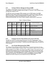
Table 12. Secure Mode Affect on ACPI States


