


Connectors Intel® Server Board Set SE8500HW4
Revision 1.0
Intel order number D22893-001
48
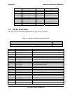
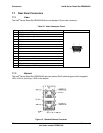
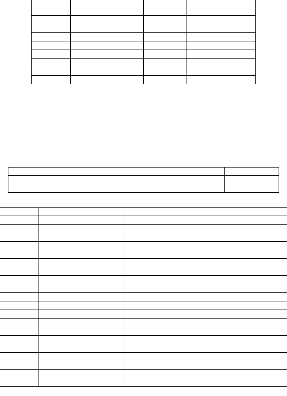
Pin Signal Pin Signal
26 SCSI(A:B)_MSG_P 60 SCSI(A:B)_MSG_N
27 SCSI(A:B)_SEL_P 61 SCSI(A:B)_SEL_N
28 SCSI(A:B)_CD_P 62 SCSI(A:B)_CD_N
29 SCSI(A:B)_REQ_P 63 SCSI(A:B)_REQ_N
30 SCSI(A:B)_IO_P 64 SCSI(A:B)_IO_N
31 SCSI(A:B)_DB_P8 65 SCSI(A:B)_DB_N8
32 SCSI(A:B)_DB_P9 66 SCSI(A:B)_DB_N9
33 SCSI(A:B)_DB_P10 67 SCSI(A:B)_DB_N10
34 SCSI(A:B)_DB_P11 68 SCSI(A:B)_DB_N11
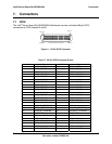
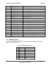
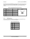
7.2 100-pin Front Panel
The Intel
®
Server Board Set SE8500HW4 has one 100-pin connector.
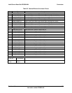
Table 18. 100-pin Front Panel Connector Pinout
Pins Signals
1,3,7,10,14,20,27,42,51,52,54,58,62,65,73,77,79,82,83,85,87,89,91,93,95,100 Ground
4,6,8,12,13,15,17,19,22,24,26,29,31,33,35,37,41,44,46,48,50,53,56,59,61,66,68,70,72 Unused
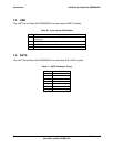
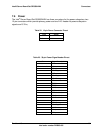
Pin Signal Name Signal Description
2 GND – RESISTOR Ground through zero ohm resistor
5 GND – RESISTOR Ground through zero ohm resistor
9 GND – RESISTOR Ground through zero ohm resistor
11 GND – RESISTOR Ground through zero ohm resistor
16 FAN1_TACH Fan 1 Tachometer signal – edges per revolution
18 FAN2_TACH Fan 2 Tachometer signal – edges per revolution
21 FAN3_TACH Fan 3 Tachometer signal – edges per revolution
23 FAN4_TACH Fan 4 Tachometer signal – edges per revolution
25 RESET_BTN Front panel reset button signal
28 FAN5_TACH Fan 5 Tachometer signal – edges per revolution
30 FAN6_TACH Fan 6 Tachometer signal – edges per revolution
32 FAN_PWM1 Zone 1 Fan PWM control signal
34 5VSTANDBY 5Vstandby to front panel
36 BP_D2D_EN Backplane D2D enable
38 5VSTANDBY 5Vstandby to front panel
39 ICH5_PDD8 IDE primary disk data 8
40 HD_ACT_N SATA Hard Drive Activity
43 BP_PWRGOOD Back Plane power good signal
45 PCI_RST_BP_N PCI reset to backplane
47 CP_PWR_LED Control Panel Power LED signal