Server Management Intel® Server Board Set SE8500HW4
Revision 1.0
Intel order number D22893-001
28
BASEBOARD
PROCESSOR SOCKETS(4)
SMS
I/F
System LPC Bus
5V
12V
3.3V
-12V
Power Button
Front Panel SDI Switch
Thermal Trip
- Chassis ID
- Baseboard ID
- Power State
CPU Voltage
INTELLIGENT PLATFORM MANAGEMENT BUS (IPMB)
Reset Button
Power Connector
To Power
Distribution
Board
Baseboard
Temp 1
Private Management Busses
RAM
CODE
(updateable)
Non-volatile, read-write storage
SENSOR
DATA
RECORDS
SYSTEM
EVENT
LOG
FRU INFO
& CONFIG
DEFAULTS
SMM
I/F
COM 1
COMM MUX
BBD COM1
CPU FRU
CPU 'Core' Temp
FRU EEPROM
EMP
DIMM SPD (16)
CPU OEM NV
Power LED
System Status LED
FANs (6)
Network Activity LEDs
PCI PME
BASEBOARD
MANAGEMENT
CONTROLLER
(BMC)
System I/F
PORTS
1.25V
3.3V Standby
LVDS-B Term
LVDS-A Term
Drive Activity/Fault LED
System Identify Button
Hot-swap
Backplane
Header
Aux. IPMB
Connector
Chip Set
ICMB
Transceiver
Header
Logic 2.5V
spkr
Identify LED
Temp Sensor
DUAL
NIC
TCO
FRU EEPROM
Front Panel Connectors
IMM
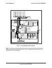
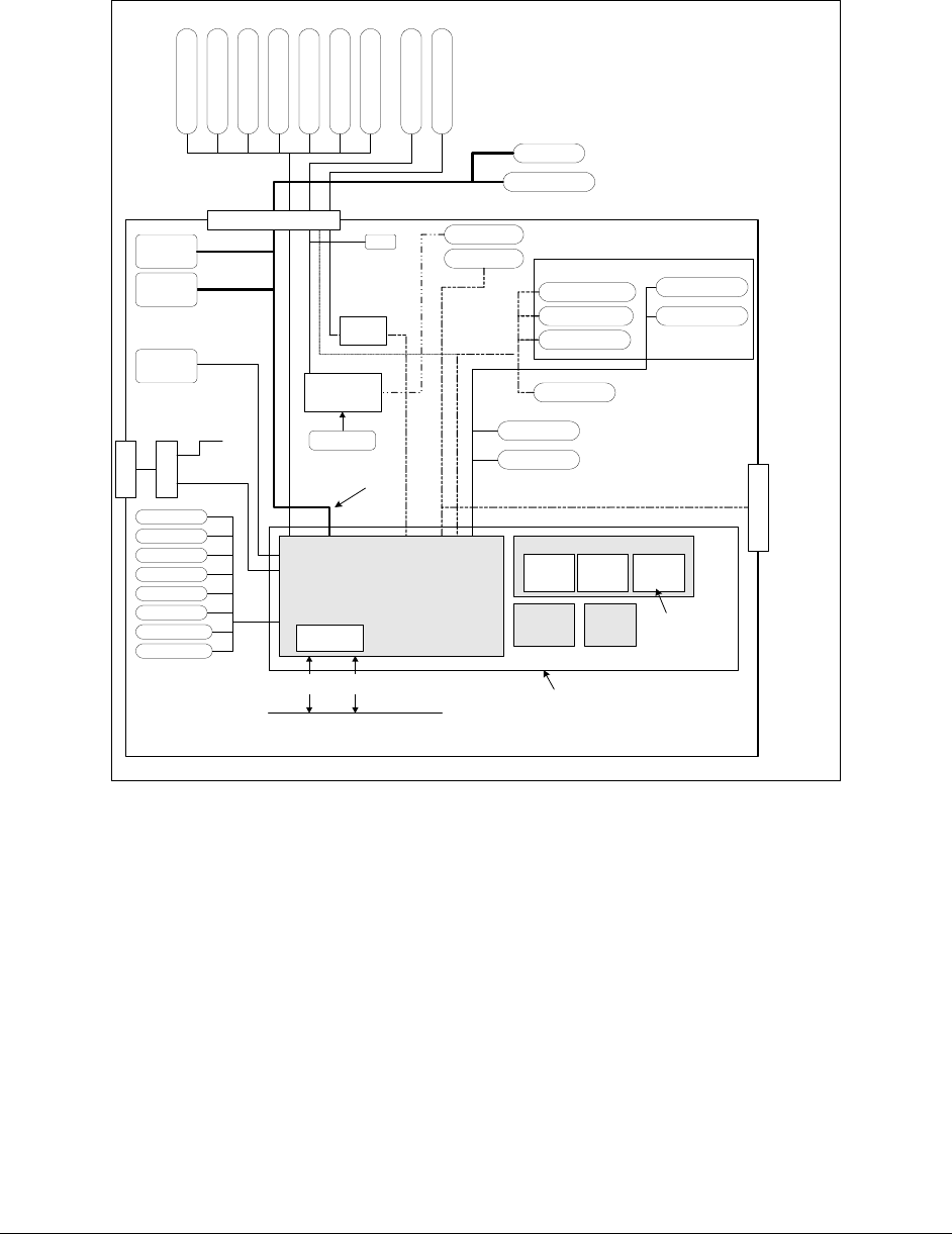
Figure 7. Server Management Block Diagram
Note: The interconnections and blocks shown are to illustrate the functional relationships
between the system management elements. They do not map directly to the exact circuit
implementation of the architecture.


