Electrical Specifications Intel® Server Board Set SE8500HW4
Revision 1.0
Intel order number D22893-001
60
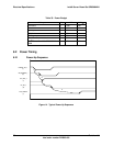
Table 35. Typical Power-Down Timings
Ref Description Max Typical Min
t1 Time from front-panel power button push, to BMC asserting the power button to the
chi
p
set. BMC debounces the
p
ower button in
p
ut for 50ms
1s 90ms 50ms
t2 Time from BMC asserting power button to chipset, until chipset responds with
SLP
_
S5
_
L. De
p
endent on chi
p
set setu
p
.
5s 4.5s –
t3 Time from when SLP_S5_L is asserted, to when BMC deasserts PS_ON_L to
complete system power-off.
1s 160ms 50ms
t4 Time from BMC deasserting D2D enable, to when it deasserts PS_ON_L to
complete system power-off.
– 100µs 0µs
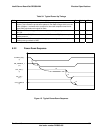
8.3 Reset
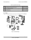
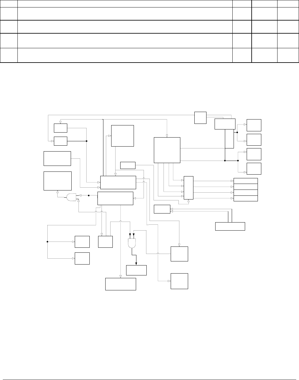
Figure 16 and Table 36 illustrate the reset routing in the Intel
®
Server Board Set SE8500HW4.
VID_PCI_RST_N
XDP1
XDP2
ICH5
NB
RESET BUTTON
FWH1
FWH2
SIO
PLD 1
PLD 3
PLD 1
Proc1
Proc2
Proc3
Proc4
PB1_RESET_N
PB0_RESET_N
IMI CONN 1
IMI CONN 2
IMI CONN 3
IMI CONN 4
IMI Hotplug
IMI_A_ISO_RST_N
IMI_B_ISO_RST_N
IMI_C_ISO_RST_N
IMI_D_ISO_RST_N
Power
Connector
PS1_PWROK
LEVEL
TRANSLATOR
OR
GATE
PB1_RESET
PB0_RESET
IMI_A_RST_N
IMI_D_RST_N
IMI_B_RST_N
IMI_C_RST_N
IMI<D:A>_RST_EN_N
NB_RESETI_N
ITP_DBR_RESET_N
FP_RST_BTN_N
LPC_FWH_LRESET_N
LPC_SIO_LRESET_N
SIO_VID_RST
Front Panel
Connector
Video
PCI_IDE_RST_N
PXH
IOP332
PXH_RESETI_N
IOP332_RESETI_N
NB_R_RESETI_N
PCI_RESET_N
ICH5_SYS_RST_N
ITP_CPU_RESET_N
BUFFER
PCI_RST_BUFF1_N
SIO_NIC_RST
PS2_PWROK
Network
PX2B_RST_N
NIC_RST_N
Figure 16. Reset Block Diagram


