


16 Intel® NetStructure™ ZT 8101 10/100 Ethernet Switch User’s Manual
Installation and Initial Setup
• All LED indicators will momentarily blink, which represents a reset of the system.
• The board status LED indicator will blink while the switch loads onboard software and
performs a self-test. After approximately 20 seconds, the LED will light again to indicate the
switch is in a ready state.
• The hot-swap LED indicator will be off.
• The port LED indicators will be off if there is no Ethernet connection and on if there is an
Ethernet connection.
Uninstalling the Board
These instructions explain the mechanical aspects of removing a Intel® NetStructure™ ZT 8101
10/100 Ethernet Switch board from a system.
1. You do not need to turn off the system power to remove a ZT 8101 board.
2. Disconnect connections at the faceplate (Ethernet and serial ports).
3. The board should be in a “safe” state to be removed or data may be lost. Signal the system that
a board is about to be removed by partially unlatching the ejectors on the board to be removed.
Do not fully open the ejectors, as this levers the board out of the enclosure and prematurely
breaks its backplane connection.
4. Wait for the blue hot swap LED on the board's faceplate to light; this indicates that board
processes have finished and the board is safe to extract. If the hot swap LED fails to light after
30 seconds, re-latch the ejectors and unlatch them again. In this case, the board is safe to
extract (though the hot swap LED may not light).
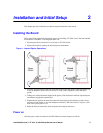
5. Once the hot swap LED lights, open the injector/ejector mechanisms fully, rotating the handles
outward until the board disengages from the backplane (refer to “” on page 15).
6. Slide the board evenly out of the enclosure.
7. Install a replacement board or cover the empty slot with a filler panel to maintain the
enclosure's shielding and cooling performance.
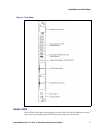
Identifying External Components
This section describes the front panel and the LED indicators of the ZT 8101switch. The front
panel consists of LED indicators, a management serial port, a toggle button, two 10/100 Ethernet
ports, and two 100/1000 Ethernet ports.