


38 Intel® NetStructure™ ZT 8101 10/100 Ethernet Switch User’s Manual
Switch Management and Operating Concepts
Even though a switch inspects a packet's IP address to determine VLAN membership, no route
calculation is performed, the RIP protocol is not employed, and packets traversing the switch are
bridged using the Spanning Tree algorithm.
A switch that implements Layer 3 (or subnet) VLANs without performing any routing function
between these VLANs is referred to as performing “IP switching.”
• IP switching does not allow packets to cross VLANs (in this case, IP subnets) without a
network device performing a routing function between the VLANs (IP subnets).
• The ZT 8101 switch does not directly support IP switching; however, you can configure the
switch to imitate this behavior by assigning IP subnets to configured VLANs and then
disabling the Routing Information Protocol (RIP). This prevents packets from crossing IP
subnets without going through an external router.
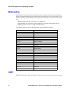
Multi-Netting
In legacy networks, multi-netting is commonly used to configure a physical router port with more
than one IP interface. In a Layer 3 switch, an IP interface is bound to a single VLAN. To
accommodate multi-netting, you must configure two or more tagged VLANs to span the same
physical ports and then assign each VLAN a different IP address.
The VLANs must include tagged ports, because untagged ports can only belong to one VLAN.
IP Path MTU Discovery
Some datagrams are sent with a don’t fragment bit set. If these datagrams are larger than the
maximum transmission unit (MTU) size of a link in the destination path, the datagram is dropped.
IP path MTU discovery alerts the host of this problem so that the host can fragment the packets to a
size acceptable to all links on the destination path.
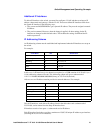
IP Interfaces
An IP interface associates an IP address with a specific VLAN, which allows the VLAN to act as
Layer 3 and be configured for RIP and multicasting protocols. Each VLAN must be configured
prior to setting up the corresponding IP interface. The switch has one pre-configured IP interface.
You can add additional IP interfaces for each user-defined VLAN.
System IP Interface
The switch’s pre-configured IP interface is called “System.” This name cannot be modified. By
default, the System IP interface is bound to the default VLAN (VID=1). This VLAN contains all
the switch's Ethernet ports.
You can assign or change the IP address of the System IP interface with a manual assignment,
BOOP, or DHCP. The switch uses the IP address assigned to the switch as the IP address for the
System IP interface.
Note: BOOTP and DHCP are only available for the System IP interface.