


CHAPTER 9
Maintaining E-Series Routers
9-10
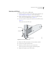
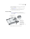
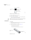
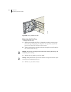
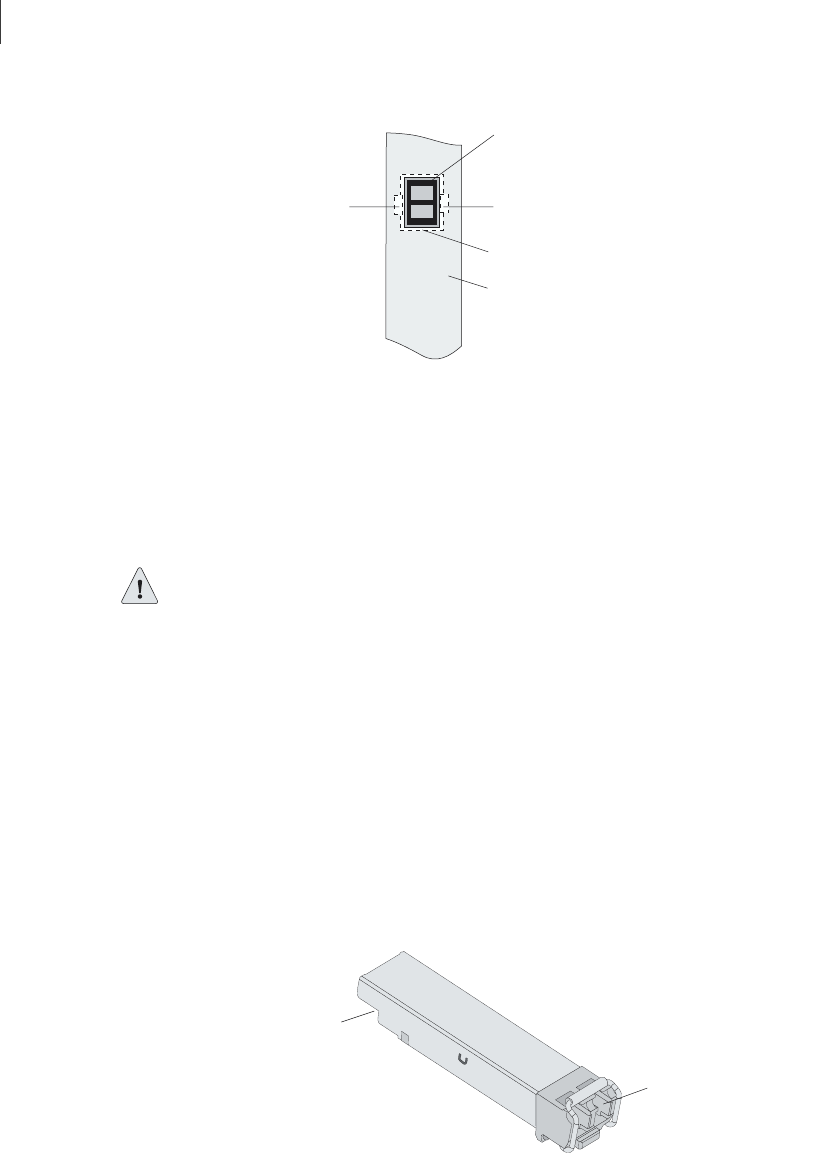
Figure 9-4 Possible release mechanisms on the SFP
5 Release the SFP and pull it out of the slot.
6 Place the SFP in an antistatic bag.
7 If you are using the redundant port on the E-series GE I/O module,
repeat steps 3 through 6 for the other SFP.
Caution: For port redundancy to operate correctly, both the primary and redundant
ports on an E-series GE I/O module must use the same type of SFP.
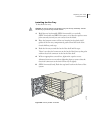
Installing SFPs
To install SFPs:
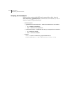
1 Put the antistatic wrist strap on your wrist, and connect the strap to
the ESD grounding jack on your system.
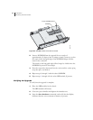
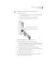
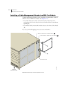
2 Identify the following items on the SFP (see Figure 9-5):
• The connection circuitry on the base
• The cable connectors on the front
The cable connectors will be protected by a dust cover.
Figure 9-5 Example of SFP
Release bar, button,
or tab
Release ring
Transceiver
Release bar, button,
or tab
Module faceplate
g013435
Cable connectors
on front
Connection circuitry
on base
g013436