


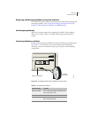


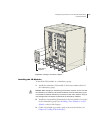
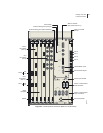
Installing Components for Line Module Redundancy
E-Series Routers
5-13
Installing Components for Line Module Redundancy
A spare line module provides redundancy for a group of identical line
modules for ERX-7xx/14xx models only.
Note: The ERX-310 router does not support line module redundancy.
For line module redundancy to operate, you must install:
• The line modules, including the spare line module
• The redundancy midplane
• The I/O modules, including the spare I/O module
For more information, see Redundancy Features in Chapter 1, E-Series
Overview.
Warning: Do not insert any metal object, such as a screwdriver, or place your hand
into an open slot or the backplane when the E-series router is on. Remove jewelry
(including rings, necklaces, and watches) before working on equipment that is
connected to power lines. These actions prevent electric shock and serious burns.
Caution: When handling modules, use an antistatic wrist strap connected to the
E-series router’s ESD grounding jack, and hold modules by their edges. Do not
touch the components, pins, leads, or solder connections. These actions help to
protect modules from damage by electrostatic discharge.
Installing the Line Modules
To install the line modules in a redundancy group:
1 Install the spare line module in the lowest-numbered slot of the
redundancy group.
2 Install the other line modules in the remaining slots. (See Installing
Line and I/O Modules earlier in this chapter).
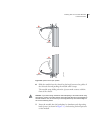
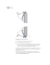
Installing the Redundancy Midplane
To install the redundancy midplane in a redundancy group:
Caution: If you do not use the halt command before removing or powering down
an SRP, the system’s NVS card may become corrupted.
1 Enter the halt command.
See E-Series System Basics Configuration Guide, Chapter 5,
Managing Line Modules and SRP Modules for information about
the halt command.