


CHAPTER 6
Cabling E-Series Routers
6-12
Warning: The wiring color code of the power cables depends on the color coding
of the DC power source installed at your site. Color code standards for DC wiring
do not exist. To ensure that the correct polarity is connected to the E-series router
power units, confirm the connection of the power cables to the + (positive) and
– (negative) leads at the power source.
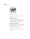
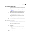
3 Remove the nuts and locking washers from the posts for the power
input (A or B) using a small insulated adjustable wrench.
4 Place one negative (neutral) cable lead on the post labeled –48 VDC.
5 Replace the locking washers and nuts, and tighten the nuts to secure
the connection.
6 Place the other cable lead on the post labeled RTN.
7 Replace the locking washer and nut, and tighten the nut to secure
the connection.
8 Attach the opposite end of Power A’s wire leads to the appropriate
leads on your power source.
Note: To provide redundancy, Power A and Power B leads should not terminate at
the same power source.
9 Place the clear plastic guard over the terminal posts, and secure it in
place by tightening the four screws.
10 Repeat steps 1–9 for each power input module in your configuration.
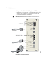
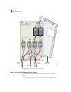
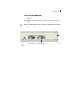
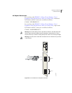
Figure 6-5 ERX-310 router, rear view (DC model)
Ground
Power B
switch
DC power
input B
DC power
input A
Power A
leads
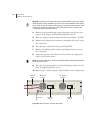
POWER B
POWER A
-48VDC RTN
ON
|
O
OFF
-48VDC RTN
ON
|
O
OFF
Power A
switch
g013753