


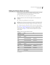
Cabling the E-Series Router for Power
E-Series Routers
6-9
Cabling the E-Series Router for Power
After you have correctly cabled the modules and I/O modules, you must
attach grounding and electrical wires before you attempt system
power-up. There are three main tasks involved:
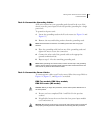
1 Switch all E-series router power switches to OFF.
Caution: Switches may have inadvertently flipped to ON during shipping and
installation.
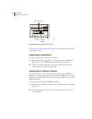
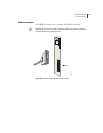
2 Connect the grounding wires to the chassis.
Warning: Always connect the grounding wires first (before connecting the power
cables) and disconnect them last when installing or servicing the E-series router.
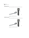
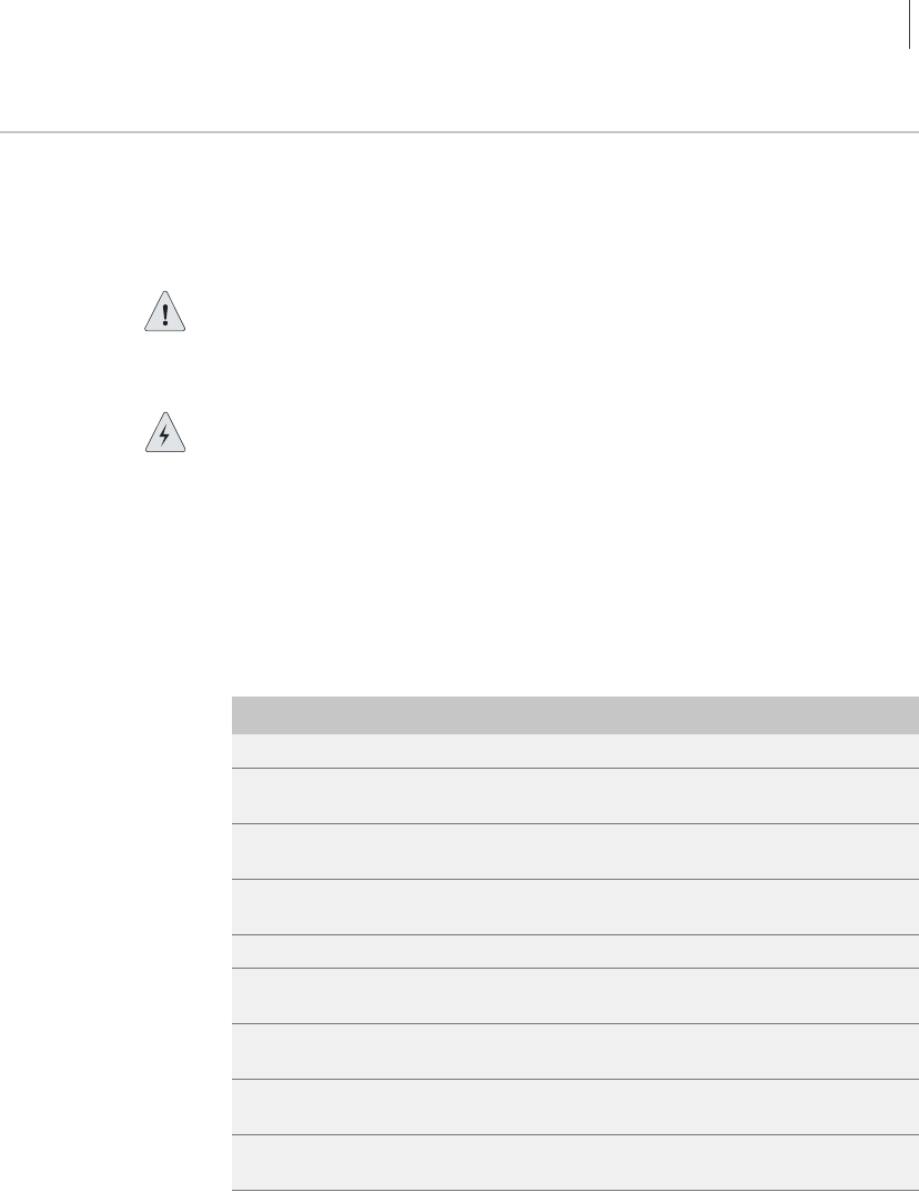
3 Connect the power cables (AC or DC) to the power input modules.
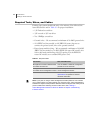
See Chapter 11, System Specifications for the power requirements for the
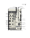
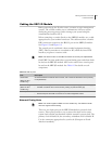
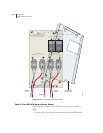
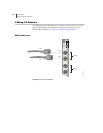
E-series router. Table 6-3 identifies the power input module cabling
requirements, and Figure 6-4 shows the main components of a power
input module.
Table 6-3 Power input module cables/wires needed
Cable/Wire From To
ERX-7xx/14xx models
One 10-AWG
ground wire
Power input module ground
terminal
Termination ground
Two 10-AWG wire
leads
Power input module Power A
–48 VDC and RTN leads
Appropriate leads on power
source No. 1
Two 10-AWG wire
leads
Power input module Power B
–48 VDC and RTN leads
Appropriate leads on power
source No. 2
ERX-310 router
One 10-AWG
ground wire
Power input module ground
terminal
Termination ground
Two 14-AWG wire
leads
a
a. DC model only
Power input module Power A
–48 VDC and RTN leads
Appropriate leads on power
source No. 1
Two 14-AWG wire
leads
a
Power input module Power B
–48 VDC and RTN leads
Appropriate leads on power
source No. 2
One AC power
cord
b
b. AC model only
Power input module AC power
IEC receptacle
Appropriate AC power supply