


APPENDIX A
Cable Pinouts
A-2
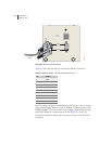
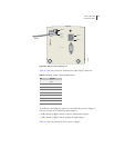
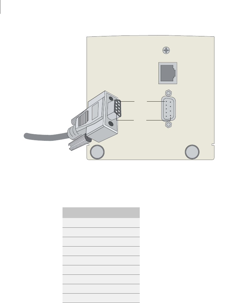
Figure A-1 SRP I/O module serial port
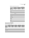
Table A-2 lists the pinout for the serial cable’s RS-232 connector.
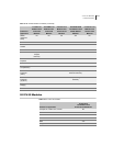
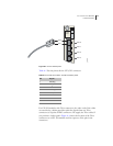
Once you have configured an IP address on the system, you can connect
using a host running Telnet over the 10/100Base-T Ethernet port on the
SRP I/O module. The router ships with a straight-through cable having a
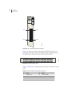
male RJ-45 Ethernet connector on each end. Figure A-2 shows the
location of the Ethernet port and the sequence of the pins in the RJ-45
connector.
CONSOLE
10/100
BASE T
RS-232
DB-9
PIN 1
PIN 9
g013771
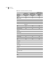
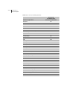
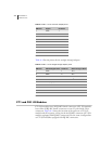
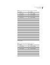
Table A-1 SRP I/O module – RS-232 serial connector pinout
Pin Signal
1 DCD
2 RXD
3 TXD
4 DTR
5 GND
6 DSR
7 RTS
8 CTS
9 RNG