


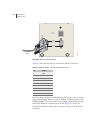
SRP I/O Module
E-Series Routers
A-3
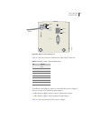
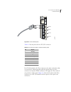
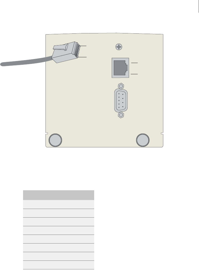
Figure A-2 SRP I/O module Ethernet port
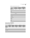
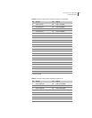
Table A-2 lists the pinouts for the Ethernet cable’s RJ-45 connector.
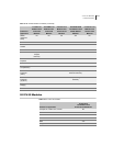
To facilitate connecting the system to a terminal, the system is shipped
with one of each of the following cable adapters:
• DB-9 female to RJ-45 female crossover null modem adapter
• DB-9 female to RJ-45 female straight-through adapter
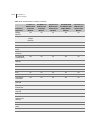
Table A-3 lists the pinouts for the crossover adapter.
CONSOLE
10/100
BASE T
RS-232
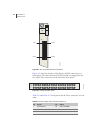
PIN 1
PIN 8
PIN 1
PIN 8
RJ-45
g013772
Table A-2 SRP I/O module – RJ-45 connector pinout
Pin Signal
1 TX +
2 TX –
3 RX +
4 n/c
a
a. n/c=no connect
5 n/c
6 RX –
7 n/c
8 n/c