


Cabling the SRP I/O Module
E-Series Routers
6-7
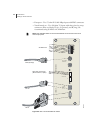
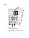
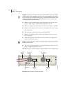
To connect the clock source input ports:
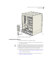
1 Depending on the connector type, complete one of the following
tasks:
• E1: Attach the BNC connector to Clock A’s external timing port.
• T1: Wrap the tip wire on pin marked T of Clock A’s external
timing port, the ground wire on G pin, and the ring wire on R
pin.
Note: You can use a wire-wrap gun to attach wires to pins.
2 Attach the opposite end of the external timing cable or wires to your
network’s clock source A.
3 Repeat steps 1 and 2 for the Clock B connections.
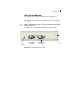
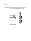
Console Ports
Note: This section applies to all E-series routers.
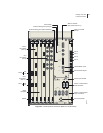
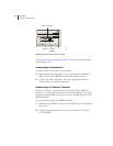
There are two ports located in the Console section of the SRP I/O
module (see Figure 6-2 and Figure 6-3) that allow management access.
• The 10/100Base-T Ethernet port accepts an RJ-45 (male)
connector, providing an out-of-band connection for LAN access
through a Telnet session or SNMP.
• The RS-232 port accepts a DB-9 (female) connector, allowing
direct CLI access from a console terminal.
The console port is considered a data terminal equipment
interface (DTE). Direct connection to a terminal or PC (which
also have DTE interfaces) requires a crossover cable.