


E-Series Modules
E-Series Routers
1-13
Caution: Do not remove the SRP module while the system is running.
For details about installing SRP modules, see Chapter 5, Installing
Modules.
SRP Module Redundancy
SRP module redundancy is available only for ERX-7xx/14xx models. See
Redundancy Features, later in this chapter, for more information.
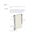
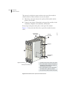
Nonvolatile Storage
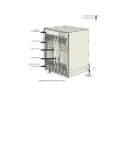
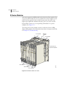
The PCMCIA slot on the front of the SRP module holds a Type II
PCMCIA nonvolatile storage (NVS) card (see Figure 1-12 and
Figure 1-13). This card is loaded with the system’s software and
configuration files. The PCMCIA card is factory installed.
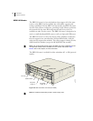
SRP I/O Module
The SRP I/O module is a single corresponding input/output module that
interfaces with the SRP module(s) through the system’s midplane. The
same SRP I/O module works with all SRP modules, but is router specific.
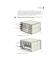
The I/O module used in ERX-7xx/14x models cannot be used in the
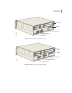
ERX-310 router, and vice versa. See Figure 1-5, Figure 1-7, and
Figure 1-9 for locations.
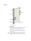
Module Details
The SRP module provides standard craft management interfaces,
including:
• 10/100Base-T – Enables access to the E-series router for Ethernet
management functions via CLI or SNMP, for example.
• RS-232 – Provides a serial connection for monitoring the system’s
hardware configuration through a PC (running terminal emulation
software) or ASCII terminal. Allows direct CLI access.
• Alarm contacts – Provide for remote indication of critical, major, and
minor E-series router alarms (ERX-7xx/14xx models only; currently
not implemented)
• External timing inputs – Provide a method of ensuring that the clock
timing used by the E-series router remains synchronized with the
network’s system clock. BNC connectors and wire wraps are available
for ERX-7xx/14xx models only.