


Chapter 5---Electronics
5-50 Model 250 Service Manual
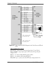
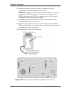
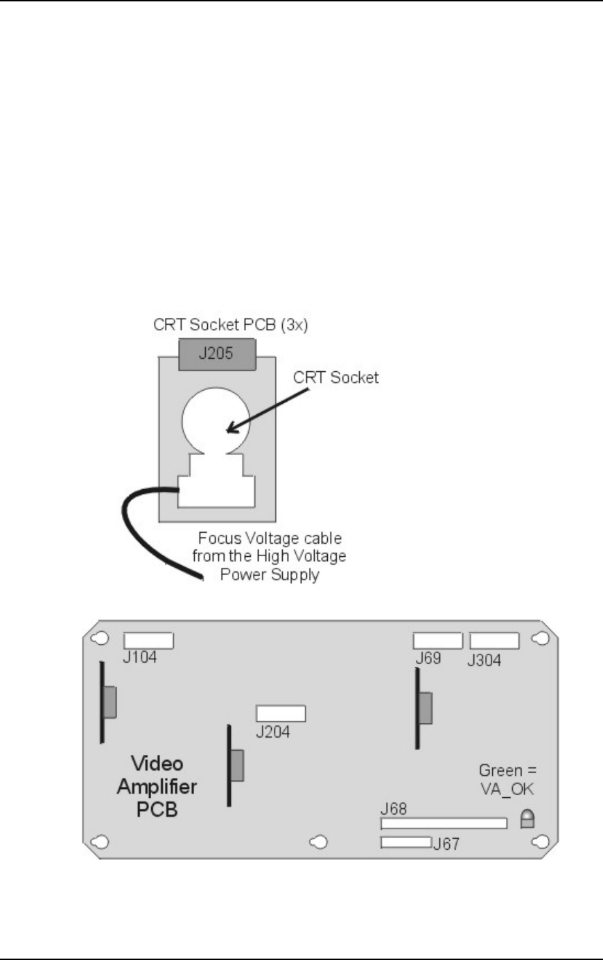
12. Disconnect the three Focus cables that run from the CRT Socket
Connectors to the Focus connectors on the HVPS.
NOTE:
Observe that each of the three Focus cables (large, red wires that
run from each CRT Socket Connector to the Focus connectors on the
HVPS) is joined near the CRT by a coupler plug and jack. Disconnect
(and label) the focus cables at these couplers.
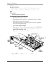
13. Loosen the six Pozi-drive Phillips-head screws that secure the Video
Amplifier PCB to the projector frame.
14. Make sure everything is out of the way, then slide the Video Amplifier
PCB toward the left so the mounting screws will clear the access holes and
remove the board from the projector.
15. Reinstall in the reverse order from above.
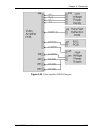
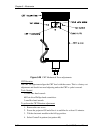
Figure 5-28
Video Amplifier PCB showing CRT Socket Connectors.