Chapter 5---Electronics
5-52 Model 250 Service Manual
Image - image light that passes through Relay Lens and focuses on photosensitive
layer on input side of ILA
®
.
CRT/Yoke Assemblies - Operation
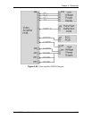
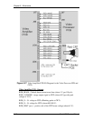
The CRTs receive image signals that come from the VICs to the Video Processor
PCB, to the Video Amplifier PCB. The image information drives an electron gun
inside the CRT. The Cathode of the CRT is a small, metal oxide disk that covers
the filament heater. The filament heater heats the Cathode causing it to emit
electrons. The electrons travel forward to the positively charged CRT Anode. As
the electrons travel forward in the CRT, they pass through control grids, each one
more positively charged than the next.
The first grid G
1
is a small aperture that is negatively charged with respect to the
Cathode. The negative bias voltage allows the beam current to be controlled by
the video signal applied between G
1
and the Cathode to modulate brightness.
The G
2
control grid restricts the beam of electrons to a narrow path and
accelerates them because of its positive voltage. The G
3
grid works with G
2
to
form an electrostatic focusing lens that focuses the electron beam on the CRT
phosphor.
The Deflection Yokes use magnetism to deflect the electron beam horizontally or
vertically inside the CRT. The Deflection Yokes deflect the electron beam at right
angles, so the Horizontal Deflection Yokes are on the top and bottom of the CRT.
The Vertical Deflection Yokes are on the left and right sides. Both the horizontal
and vertical deflection waveforms come from the Horizontal Vertical Deflection
PCB. Geometric, Convergence, and Shading correction information is add to the
deflection waveforms to adjust them so they create a centered, linear uniform
image on the screen.
Each CRT is encased in a metal shroud made of Mu metal. This shroud protects
the CRT from stray magnetism from PCBs, cooling fan motors and the
magnetism from other CRTs. The stray magnetism can influence the CRT Yoke
magnetism causing noise and distortion on the screen.
CRT/Yoke Assemblies - Service Adjustments
NOTE:
It is recommended that the CRT Mechanical Focus procedure and the
CRT Rotation procedure be done sequentially. This means that the CRT
Mechanical Focus procedure should be performed immediately followed by the
CRT Rotation procedure or vice versa. The reason for this is there are two
setscrews, one on either side of the Guide Plate, that hold the CRT in position.
Loosening the setscrews to perform one adjustment may cause the other
adjustment to change; therefore, both adjustments should be performed at the
same time.


