


Chapter 8---Software and Protocol
8-2 Model 250 Service Manual
!
Cursor=Block & Blink
!
Terminal Font=Fixedsys 15
!
Translation=None,
!
Show Scroll Bars=On
!
Buffer Lines=100
!
Use Function Arrow
!
Control Keys for Windows=Off
Select OK.
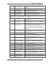
6. Under Settings select Text Transfer=Standard Flow Control. Select OK.
7. Under Settings select Communications and choose;
!
Connector=select the PC port being used
!
Baud Rate=9600 or 19200 (depending on the System Controller
Switch block Pos 4-see note below this step)
!
Data Bits=8, Stop Bits=1, Parity=None
!
Parity Check=Off, Carrier Detect=Off, Flow Control=XON/XOFF
Select OK.
NOTE:
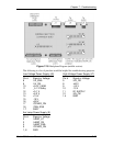
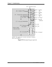
Switch position 4 on the switch block at the card edge of the
System Controller (see Figure 7-2) controls the baud rate for Serial Port A
for the Boot Manager and System Software. Down=9600, Up=19200.
Ensure the other SCB switches (1, 2, and 3) are in the Down position.
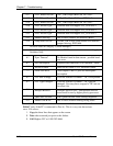
8. Turn the projector circuit breaker on while depressing and holding down
the service mode switch on the System Controller PCB (see Figure 7-1).
Verify that "Boot Manager" appears on the terminal monitor. The Power
On LED stays Red.
Alternate for Step 9: In "Power Off" Standby mode, Press "Control, Shift
+ _ (underscore), hex "IF (international keyboard may vary in key
placement).
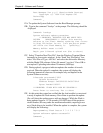
9. The following should be displayed on the Windows Terminal screen
(where x.x.0 is the currently loaded Boot Manager version (e.g. 0.9.0 or
1.1.0).
–Boot Manager Ver x.x.0 (Service Mode Startup)
–Copyright (c) 1994 Hughes JVC Technology
–Command: _
10. Verify that the Boot Manager version is correct. If it is necessary to update
the Boot Manager, perform the following steps. If the Boot Manager is
already up to date, skip to Step 12A to update the System Software.
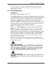
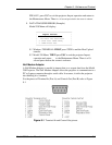
11A. Enter the command "loadboot" at the prompt. You should see the
following output:
Command: loadboot
Boot Manager software update procedure