


Chapter 2---System Description
2-6 Model 250 Service Manual
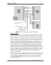
Printed Circuit Boards (PCB)
The Model 250 Projector has eight main PCBs:
!
System Controller PCB - System Controller PCB controls much of the
electronics system. It uses digital and analog circuitry to generate Menu
and internal pattern overlays, and directs convergence correction and
shading information. It controls the IIC data bus that sends geometric
correction and VIC selection data. The System Controller PCB controls
and monitors the status of power supply operations during and after the
projector is powered ON.
!
Raster Timing Generator PCB - The Raster Timing Generator PCB
generates an internal sync for the PLL (Phase Lock Loop) circuitry. It
provides sync detection and selection. It also generates the blanking pulse,
provides horizontal and vertical phase adjustments, and Interlace
detection.
!
Video Processor PCB - The Video Processor PCB receives external image
and sync signals and sends horizontal sync, vertical sync, and green sync
signals to the Raster Timing Generator PCB. It adds Contrast, Brightness,
Sensitivity and Threshold adjustments to the image signals and sends the
image signals, G
2
control lines, and G
1
bias to the Video Amplifier PCB.
!
Horizontal Vertical Deflection PCB - The Horizontal Vertical Deflection
PCB supplies the deflection waveforms that drive the deflection yokes on
the CRTs for the horizontal and vertical raster. It integrates the geometry
correction such as pincushion, keystone, and vertical linearity onto the
horizontal deflection waveform and adjusts the horizontal and vertical
center raster.
!
Convergence Deflection PCB - The Convergence Deflection PCB
generates the horizontal and vertical convergence correction waveforms. It
generates the horizontal and vertical Dynamic Focus Parabola used by the
High Voltage Power Supply. The Convergence Deflection PCB also
provides the ILA
®
bias and sensitivity.
!
Scan Reversal PCB - the Scan Reversal PCB reverses the deflection
waveforms for both the horizontal and vertical axes for floor/ceiling
mounting and front/rear mounting. It also provides scan failure detection
to protect the CRT.
!
Video Amplifier PCB - The Video Amplifier PCB amplifies the video
signals and drives the cathodes for all three CRTs. It senses the cathode
beam current and regulates the G
1
and G
2
for all the CRTs. The Video
Amplifier PCB also provides phosphor protection for all three CRTs and
CRT interface for the Focus, Heater Voltage, and Arc ground.
!
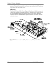
Backplane - The Backplane sits in the back of the Electronics Module.
The System Controller PCB, Raster Timing Generator PCB, Video
Processor PCB and the VICs plug into directly the Backplane PCB. It