


Chapter 3---Electrical
Model 250 Service Manual 3-13
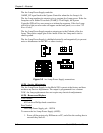
Table 3-1
HVPS -
P45 I/O Pinout
PIN # Description PIN # Description
1 GND (+80V) 9 +15V
2 GND (+15V) 10 -15V
3 GND (-15V) 11 G1 SUPPLY
4 GND (G1) 12 /HV_ENA
5 /HV_OK 13 V PARABOLA
6 H PARABOLA 14 H DRIVE (HVPS_SYNC
7 GND (DAF)
8 +80V
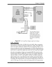
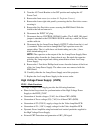
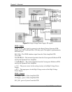
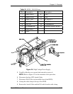
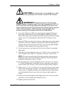
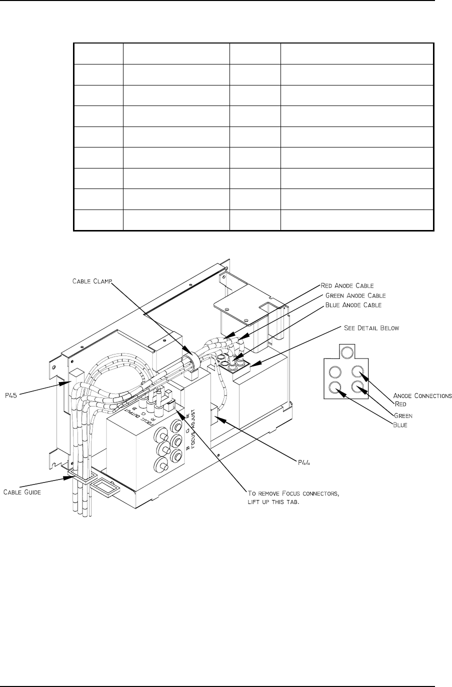
Figure 3-6
High Voltage Power Supply.
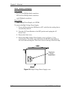
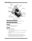
5.
Carefully slide the cover upward and outward to remove it.
NOTE
: Refer to Figure 4-5 for the remainder of this procedure.
6.
Disconnect the three CRT Anode Cables.
7.
Disconnect P44-G2 Out (at the middle-front of the HVPS).
8.
Unsnap the cable clamp at the top of the HVPS.
9.
Remove the Anode Cables and the P44 cable from the cable clamp.