


Chapter 5---Electronics
Model 250 Service Manual 5-15
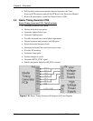
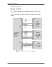
The G
2
voltage accelerates the electrons that are emitted from the cathode of the
CRT. The CRT filament emits the electrons and G
1
voltage regulates the amount
of electrons that are emitted from the cathode. The G
2
voltage is adjusted through
the menu (Black Level). The Video Processor PCB receives the G
2
control data
for each color through the IIC bus and sends an analog voltage to the Video
Amplifier PCB to control the G2 voltage.
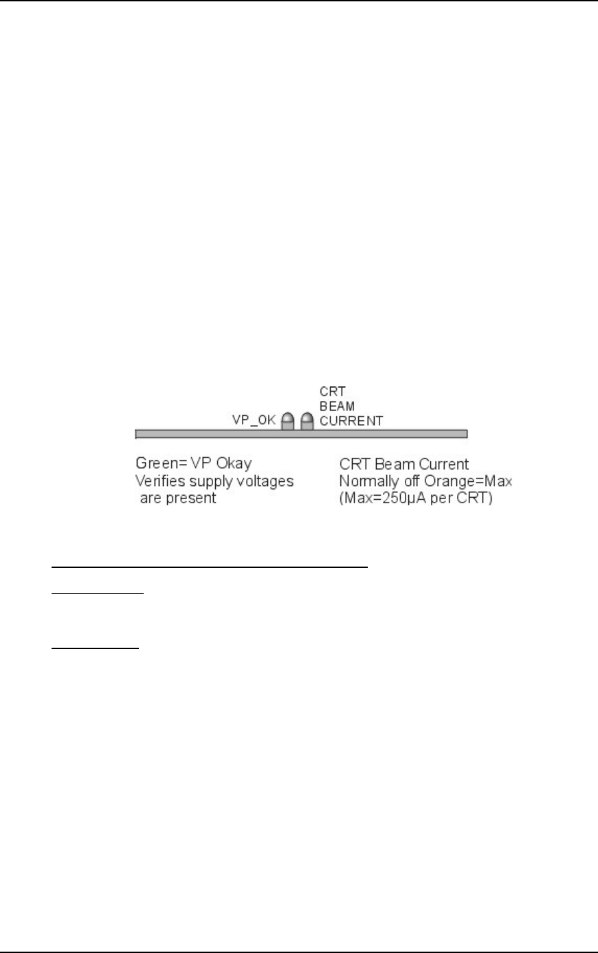
The Video Processor PCB protects the CRTs from excess beam currents to
prevent it from burning the phosphor. The Video Amplifier PCB sends a sample
of the beam current (RGB_BEAM) for each CRT back to the Video Processor
PCB. The Video Processor PCB compares this sample to a preset value. If the
sample beam current is higher than the preset value, the Video Processor PCB
reduces the contrast for the CRT with high beam current. If the CRT beam current
is still high, it then reduces the G
2
voltage. The maximum beam current is 250 µA
per CRT.
The Video Processor PCB receives the G1_BIAS signal from the System
Controller PCB through the IIC bus and sends a voltage to the Video Amplifier
PCB to set the brightness level.
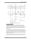
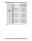
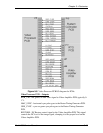
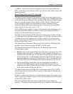
Figure 5-9
Video Processor PCB LEDs.
Video Processor PCB - Remove and Replace
Tools Needed
#1 Pozi-drive Phillips-head screwdriver
Parts Needed
Video Processor PCB - p/n 105234
To remove the System Controller PCB:
1. Power off the projector by IR Remote or PC, and allow the cooling fans to
run until they shut off automatically.
2. Turn the AC Circuit Breaker to the OFF position and unplug the AC
Power Cord.
3. Disconnect all the external source video cables and control cables.
4. Remove the rear cover.
5. Remove the Back Panel by removing the nine Pozi-drive Phillips-head
retaining screws using the #1 Pozi-drive Phillips screwdriver.