Chapter 5---Electronics
5-28 Model 250 Service Manual
Horizontal Vertical Deflection PCB - Remove and Replace
The Horizontal/Vertical (H/V) Deflection PCB is located in the upper portion of
the Electronic Module card cage.
Tools Needed:
#1 Pozi-drive Phillips-head screwdriver
Parts Needed:
Horizontal Vertical Deflection PCB p/n 105236
To remove the Horizontal/Vertical (H/V) Deflection PCB:
1. Power off the projector by IR Remote or PC, and allow the cooling fans to
run until they shut off automatically.
2. Turn the AC Circuit Breaker to the OFF position and unplug the AC
Power Cord.
3. Remove the rear cover.
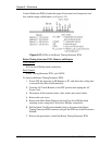
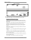
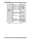
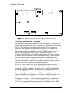
4. Disconnect six connectors; J34, J35, J36, J41, J42, and J43 (see Figure
5-15). Move the cables out of the way.
5. Loosen (it is not necessary to remove) the 5 Pozi-drive Phillips-head
screws that secure the Horizontal Vertical Deflection PCB to the
electronic module cage.
6. Remove the Horizontal Vertical Deflection PCB by sliding it toward the
left side of the projector (this is the upward direction if the electronic
module is tilted up) so that the mounting screws clear the access holes.
Then lift the side of the PCB that is nearest the front of the projector first
and angle it upward so that the side closest to the rear clears the lip of the
electronic module frame. Be careful when removing or reinstalling the
PCB to avoid damaging it on the fan screws or cable clamps.
7. Reinstall the Horizontal Vertical Deflection PCB by lowering the side that
is nearest to the rear of the projector in first until it clears the electronic
module edge, then lowering the other side. Carefully fit the board over the
mounting screws and slide the board into position. Tighten the screws and
reconnect the connectors.
5.7 Convergence Deflection PCB
Convergence Deflection PCB - Main Functions
!
Generation of various waveforms for the horizontal and vertical
deflection.
!
Height control
!
Generation of waveforms for dynamic focus
!
Various geometry correction functions for the horizontal and vertical axes


