


Chapter 4---Optical
Model 250 Service Manual 4-15
NOTE:
Reset the ILA
®
bias after setting the Compensator and check G
2
Sensitivity Offset, and Threshold Offset level (see Model 250 User’s
Guide, section 5.8 Black Level G
2
and Sensitivity Offset).
ILA
®
Overlap
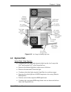
This adjustment positions the ILA
®
assemblies in their sockets so that the image
from each ILA
®
will overlap (be placed on top of) the other two ILA
®
s. Make this
adjustment whenever replacing an ILA
®
.
Tools Needed
4-mm hex-head wrench
Flathead screwdriver
Parts Needed
No parts are needed
To determine if this adjustment is necessary:
1. Power the projector ON and allow it to stabilize for at least 30 minutes.
2. Record the value of the ILA
®
bias for red, green and blue. Return the
ILA
®
s to these levels when this procedure is complete.
3. Under the System-Preferences menu, verify that the “Shutters on Hide”
box is unchecked.
4. Use the HIDE key to hide red, green and blue.
5. Increase the ILA
®
bias for all three colors to maximum. The image on the
screen should be white with some colors at the edges.
6. Check the right, left, top, and bottom edges of the images on the screen.
Using the green image as a reference, compare the edges of the red and
blue image to the green image.
7.
NOTE:
If the green ILA
®
has been replaced, reference green to the blue or
red image.)
8. If there is a red or blue border on the left, right, top or bottom edge, the
ILA
®
s overlap and need adjustment. If both the red and blue overlap, the
border will be yellow. In either case, proceed with the adjustment below.
9. If there is no overlap, reset the ILA
®
biases to their previous levels from
Step 1.
To perform an ILA
®
Overlap adjustment:
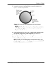
10. Continue with all three colors hidden.
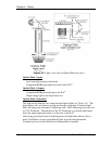
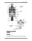
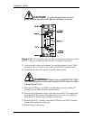
11. Loosen the two wing nuts at the top of the ILA
®
assembly (see Figure
4-10).
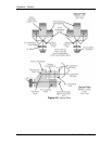
12. If the overlap is at the left or right, grasp the ILA
®
assembly and slide it to
the right or left so that the edges coincide with the edges of the other two
ILA
®
assemblies.