


Chapter 4---Optical
4-16
Model 250 Service Manual
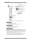
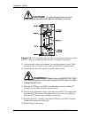
CAUTION!
To avoid damaging the connector,
grasp the ILA
®
assembly itself,
not
the connector at the top.
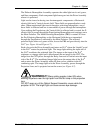
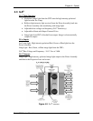
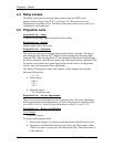
Figure 4-10
ILA
®
Assembly top view. The overlap screws shown are under
the ILA
®
. They are visible only after the ILA
®
assembly is removed.
13. If the overlap is at the top or bottom, be sure the projector is level. Slide
the spring clip (see Figure 4-10) at the top of the ILA
®
assembly back.
14. Loosen the two hex nuts, using a 4-mm hex-head wrench.
WARNING
!!!
Always wear an ANSI/ASTM 10,000
volt rated safety glove when working around CRTs due to the High
Voltage present there.
15. Slide the ILA
®
/Relay Lens/CRT Assembly back and remove the ILA
®
assembly (it will slide out with some resistance).
16. There are two adjustment screws at the bottom of the ILA
®
assembly that
move the ILA
®
up or down. Turn these screws in or out very slightly to
allow the ILA
®
to seat lower or higher, as necessary.
17. Reinstall the ILA
®
assembly, slide the ILA
®
/Relay Lens/CRT Assembly
forward and replace the spring clip.
18. Repeat Step 4 as necessary.