


Chapter 5---Electronics
Model 250 Service Manual 5-43
7. Power ON the projector and allow it to stabilize for a minimum of 15
minutes. It is recommended that the projector be operating for a least one
hour before performing shading adjustments.
8. When changing jumpers for floor or ceiling screen projection, Centering,
Convergence and Shading must be rechecked.
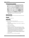
Scan Reversal PCB - Remove and Replace
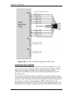
The Scan Reversal PCB is located on the front side of the Electronic Module (see
Figure 5-2).
Tools Needed
#1 Pozi-drive Phillips-head screwdriver
Parts Needed
Scan Reversal PCB p/n 102585
To remove the Scan Reversal PCB:
1. Power off the projector by IR Remote or PC, and allow the cooling fans to
run until they shut off automatically.
2. Turn the AC Circuit Breaker to the OFF position and unplug the AC
Power Cord.
3. Remove the projector rear cover.
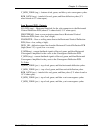
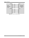
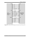
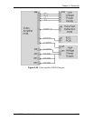
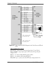
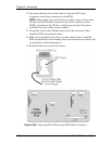
4. Disconnect seven connectors (seeFigure 5-25): J52, J54, J64, J65, J66, J50
(or J50A), and J100 (or J101). To remove, push in slightly, squeeze the
tabs, and then pull connector out.
5. Move all cables out of the way.
6. Remove the four Pozi-drive screws (see Figure 5-25) and lift the board off
the Electronics Module.
7. Reinstall in the reverse order from above.
5.9 Video Amplifier PCB
Video Amplifier PCB - Main Functions
!
Amplification of video signals and driving the cathode of all three CRTs
!
Sensing the cathode beam current for all three CRTs
!
G
1
regulator for all three CRTs
!
Blanking drive section
!
Phosphor protection for all three CRTs
!
G
2
regulator and adjustment of black level (screen) for all CRTs
!
DC restoration for the video signals
!
CRT interface for focus, heater voltage and ARC ground