Chapter 3---Electrical
3-4
Model 250 Service Manual
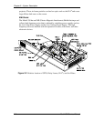
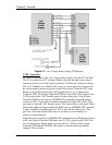
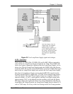
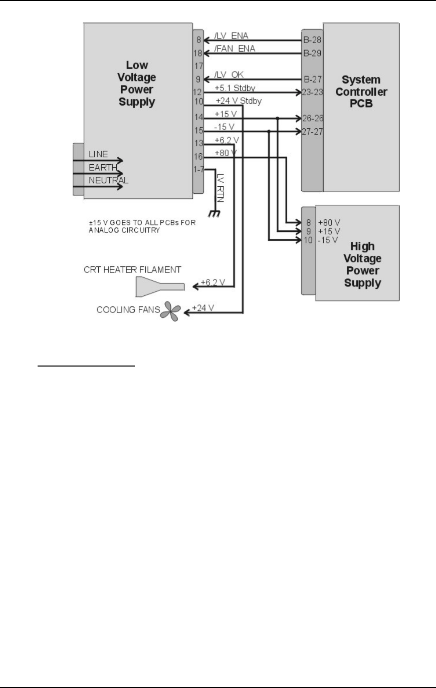
Figure 3-1
Low Voltage Power Supply I/O Diagram.
LVPS - Operation:
AC power is delivered to the Low Voltage Power Supply from the AC line filter.
The AC is rectified to a DC Voltage, filtered, and goes through a power factor
correction circuit to force the current waveform to follow the voltage waveform.
The +5.1V Standby is on whenever AC power is connected to the projector and
the circuit breaker on the rear panel is in the ON position. When the AC Circuit
Breaker is in the ON position, the LVPS supplies the +5.1 V to the System
Controller PCB. The System Controller PCB drives the /FAN_ENA signal to the
LVPS to turn on the +24V Standby power for the cooling fans. If the System
Controller PCB does not receive a POWER ON command from an IR remote
control or a PC, it waits about 10 minutes and then tells the LVPS (/FAN_ENA
goes high) to shut off +24V Standby power. This shuts off the cooling fans. More
importantly, after the System Controller PCB receives a POWER OFF command
it waits 10 minutes, and then tells the LVPS to shut off the cooling fans. This
gives the Arc Lamp and the PCBs time to cool down to avoid damage or
reduction of operating life.
When the projector receives a POWER ON command from an IR Remote Control
or PC, the System Controller PCB sends the /LV_ENA signal to the LVPS. The
Low Voltage Power Supply needs to receive the /LV_ENA from the System
Controller PCB and the /COVER_ON signal to activate all the non-standby
voltages. These include:


