Chapter 7---Troubleshooting
7-20
Model 250 Service Manual
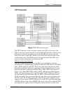
Amplifier PCB the /SWEEP_OK becomes the /VA_OK signal and checks the
supply voltages such as +15 V, +6.2 V and +80 V. The /VA_OK LED
illuminates (see Video Amplifier PCB LED) if the supply voltages are present and
the /SWEEP_OK is low. The /VA_OK also goes to the High Voltage Power
Supply. On the High Voltage Power Supply, a logical “high” shuts down the high
voltage amplifier that generates the Anode, Focus, and G
2
voltages. The /VA_OK
signal also goes to the Video Processor PCB where a logical “high” shuts down
the G
2
control voltages.
Yoke Connector Detection
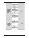
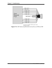
The CRT Protection circuit also ensures that CRT Yoke connectors are properly
installed. It does this with the H_LOCK+/- circuit. This series circuit goes from
the Horizontal Vertical Deflection PCB to the Scan Reversal PCB, through each
CRT Yoke connector, and back to the Horizontal Vertical Deflection PCB. The
H_LOCK+ has +15 V applied to it on the Horizontal Vertical Deflection PCB. If
all the CRT Yoke connectors are properly installed H-LOCK+ and H_LOCK-
will both measure +5 V. If the any one of the connectors is not properly installed,
H_LOCK+ will measure +15 V and H_LOCK- will measure 0 V. If H_LOCK- is
at 0 V. This shuts down the horizontal amplifier circuit that generates the
horizontal deflection waveform.
CRT Beam Current
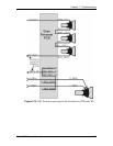
Another function the CRT Protection circuit performs is to monitor the beam
current of each CRT. The Video Amplifier PCB outputs a current sense line
(RED, GRN, and BLU BEAM) from each image amplifier circuits. The Video
Processor PCB receives these current sense lines and compares them to a
reference. If the beam current of any CRT exceeds 250 µA, the Beam current
LED illuminates orange, and the Video Processor PCB reduces Contrast. If
reducing Contrast does not bring the CRT beam current below 250 µA, the Video
Processor PCB reduces the G
2
voltage until the beam current drops below the
limit.


