Chapter 3---Electrical
Model 250 Service Manual 3-9
2.
Turn the AC Circuit Breaker to the OFF position and unplug the AC
Power Cord.
3.
Remove the front cover (see section 6.1 Projector Covers ).
4.
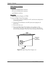
Remove the lower-right-side panel by removing the five Pozi-drive screws
securing it.
5.
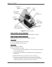
Remove the five Pozi-drive screws securing the EMI Shield. Slide the
shield to the left and remove it.
6.
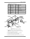
Disconnect the INPUT AC plug.
7.
Disconnect the two CONTROL SIGNALS cables. The /LAMP_OK signal
jumper is attached to the CONTROL SIGNAL cable by a cable tie. Do not
cut this cable tie.
8.
Disconnect the Arc Lamp Power Supply OUTPUT cables from the (+) and
(-) terminals. Take care not to damage the 470µf capacitor across the
output cables. The (+) cable has a red shrink tubing on it; the (-) has a
black shrink tubing on it.
NOTE
: The capacitor on the output of the Arc Lamp Power Supply filters
transient spikes from the Arc Lamp when it arcs. Re-attach the capacitor
with the Arc Lamp output leads during reinstallation of new Arc Lamp
Power Supply.
9.
Remove the 1 Pozi-drive Phillips-head screws from the bottom of the front
of the Arc Lamp Power Supply. The other screw was removed with the
EMI Shield.
10.
Carefully slide the Arc Lamp Power Supply out of the projector.
11.
Replace the Arc Lamp Power Supply in the reverse order.
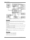
High Voltage Power Supply (HVPS)
HVPS - Main Functions
The High Voltage Power Supply provides the following functions:
!
Phase locked loop circuit for synchronization of the High Voltage Power
Supply to the HVPS_SYNC
!
Generation of Anode voltages (25 kV) for all three CRTs (RGB)
!
Generation of Focus voltage (G3) (7 kV) for all three CRTs (RGB)
!
Generation of G2 (1200 V) supply voltage for the Video Amplifier PCB.
!
Generation of G1 (-150 V) supply voltage for the Video Amplifier PCB.
!
Dynamic Focus Amplifier using horizontal and vertical parabolas supplied to
the High Voltage Power Supply.
!
External CRT Protection and generation of /HV_OK signal


