Chapter 7---Troubleshooting
7-6
Model 250 Service Manual
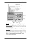
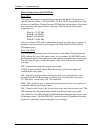
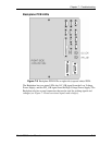
Sync - There are three sync test points: H sync for the horizontal sync pulse, V
sync for the vertical sync pulse, and G sync, which is a combination of the
horizontal and vertical sync pulses that are carried with the green image signal.
External - There are three external image test points: R ext, for the red external
image signal, G ext for the green external image signal, and B ext for the blue
external image signal. The external signal is the image signal coming into the
Video Processor PCB from the VIC.
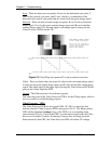
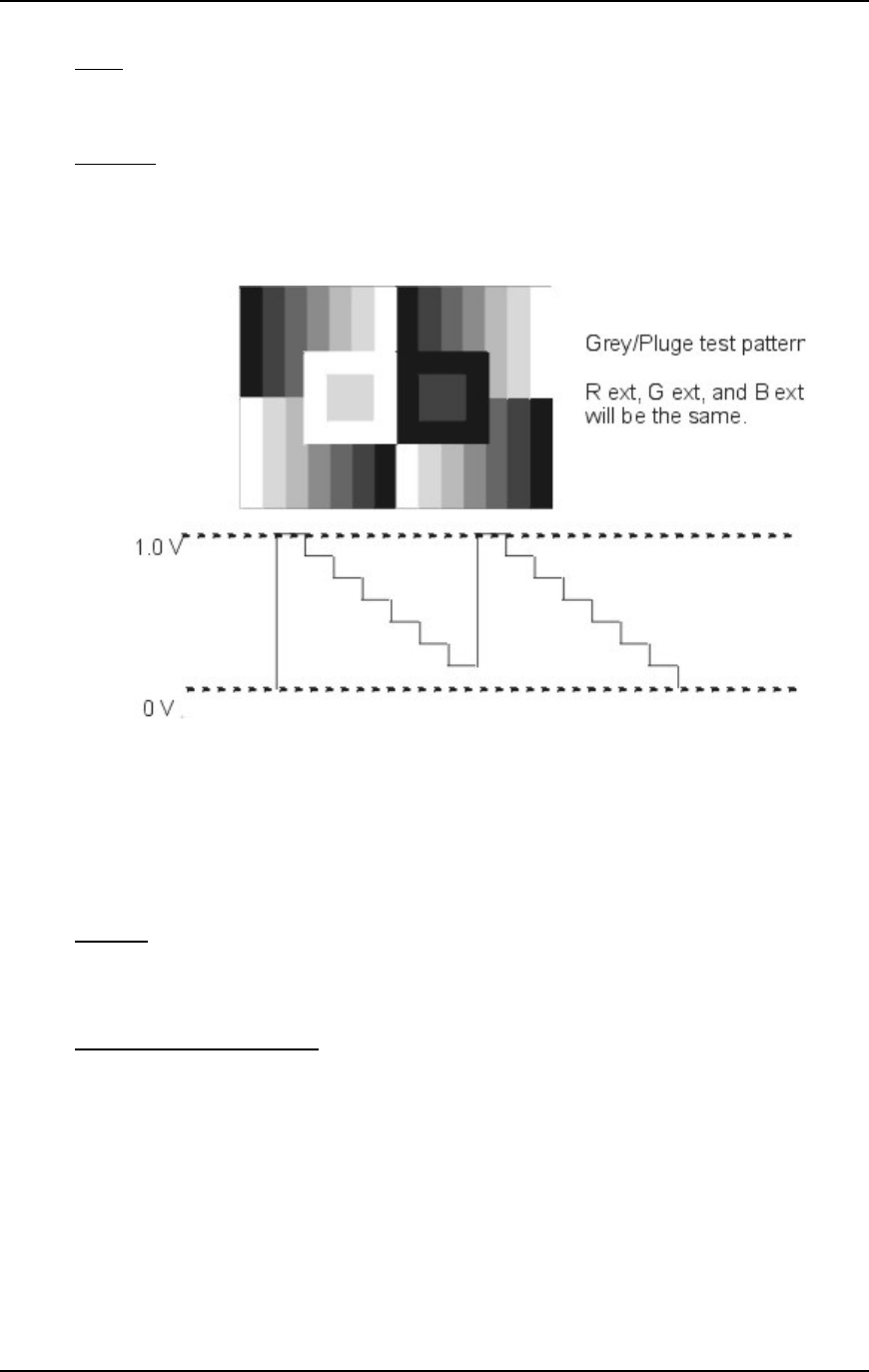
Figure 7-5
Grey/Pluge (test pattern #7) with associated waveform.
Video - There are three video test points: R video for the red output image signal,
G video for the green output image signal, and B video for the blue output image
signal. The video signal is the image signal leaving the Video Processor PCB and
going to the Video Amplifier PCB.
Ground - The Gnd test point is for reference ground.
The other test point on the Video Processor PCB is for the /Clamp signal, which is
not very useful for troubleshooting purposes.
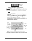
Video Processor - LEDs
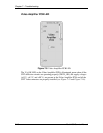
The Video Processor PCB has two green LEDs. VP_OK is a status line that
indicates that the Video Processor PCB is has power (±15 V). The Beam current
LED will be illuminated orange if any of the CRTs is at or exceeding beam
current limit (250 µA). If any of the CRTs is at the beam current limit, the Video
Processor will reduce Contrast. If reducing Contrast does not bring down the
beam current for that CRT, the Video Processor PCB will reduce G2 voltage.


