


Chapter 4---Optical
4-14
Model 250 Service Manual
ILA
®
Operation
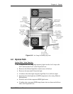
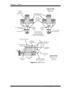
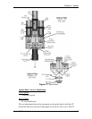
The ILA
®
plays a critical part in bringing the image to the screen. The ILA
®
receives the image light when the CRT projects the image through the Relay Lens
and focuses it onto the photoconductive layer on the input side of the ILA
®
. The
image does not pass directly through the ILA
®
but is transferred by a change of
impedance of the photoconductive layer to the Liquid Crystal Layer on the output
side of the ILA
®
. The light coming from the Arc Lamp enters the output side of
the ILA
®
and passes through the Liquid Crystal layer. Here the polarized light is
rotated according to the orientation of the liquid crystal molecules. It then reflects
off the mirror and passes back through the liquid crystal layer. The polarized light
it is rotated again and then exits the ILA
®
. The amount the liquid crystal rotates
the polarized light depends on the ILA
®
Bias, ILA
®
Sensitivity (frequency), and
CRT brightness (Sensitivity and Threshold).
ILA
®
Service Adjustments
ILA
®
Bias and Sensitivity Adjustment
The ILA
®
has adjustable bias and frequency (sensitivity). The ILA
®
bias and
sensitivity are adjusted by software through the menu (see Model 250 User’s
Guide, section 5.6 Setup Adjustments). The ILA
®
bias is individually adjustable
for each ILA
®
; the ILA
®
sensitivity (frequency) adjusts all the ILA
®
s together.
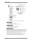
Super Contrast ILA
®
Compensator Adjustment
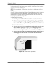
The offstate level can be adjusted on Super Contrast ILA
®
s. The Compensator
adjustment moves a lever on the top of each Super Contrast ILA
®
to a null
position. The null position is where the offstate level is as dark as possible. The
Compensator is set at the factory and should not need adjustment. Perform this
procedure when replacing an ILA
®
assembly or if the Compensator adjustment
lever has been inadvertently moved.
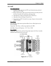
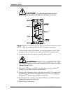
To set the Super Contrast ILA
®
Compensator:
1. Power the projector ON and allow it to stabilize for at least 30 minutes.
2. Remove the rear cover and tilt the Electronics Module up.
3. Under the System-Preferences menu, verify that the "Shutters on Hide"
box is checked.
4. Use the HIDE key to hide red and blue.
5. Disconnect the connector from the top of the green ILA
®
assembly.
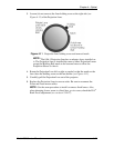
6. Move the Compensator lever (this lever is just in front of the ILA
®
connector) to the right and left until the darkest level appears on the
screen.
7. Reconnect the ILA
®
connector to the green ILA
®
.
8. Repeat the above steps for the red ILA
®
and blue ILA
®
. Block the light
from the other two ILA
®
s each time, using the HIDE key.
9. Replace the rear cover.