


Chapter 5---Electronics
5-32 Model 250 Service Manual
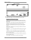
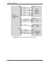
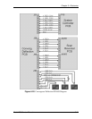
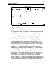
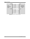
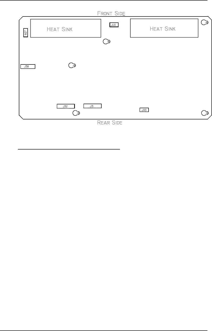
Figure 5-21
Physical layout of the Convergence/Deflection PCB.
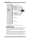
Convergence Deflection PCB - Operation
The Convergence Deflection PCB performs four main functions. It generates the
vertical deflection sawtooth waveform. It generates the square waves that bias the
three ILA
®
s. It controls the amplitude of waveforms used for convergence
corrections, and it generates the parabolic waveform used for dynamic focus.
The Convergence Deflection PCB receives the V_DRIVE signal, which is a
sample of the vertical sync, from the Raster Timing Generator PCB. The
Convergence Deflection PCB has a Waveform Generator Section that generates
the vertical deflection sawtooth waveform and outputs the V_RAMP signal that
drives the vertical amplifier on the Horizontal Vertical Deflection PCB. The
vertical amplifier drives the CRT deflection coils for vertical deflection. The
Waveform Generator also generates the parabolic waveforms used for geometry
correction such as bow, pincushion, keystone, and linearity
Each of the ILA
®
s is biased by a square wave generated by the Waveform
Generator on the Convergence Deflection PCB. Each ILA
®
is biased separately
through the ILA
®
Bias command in the Factory Adj. Menu. The commands are
received through the IIC interface. As the square wave that drives the ILA
®
is
increased, the ILA
®
becomes more sensitive to the image light that strikes the
photoconductive layer and outputs more light. The command that controls the
frequency of the ILA
®
bias square wave is referred to as ILA
®
Sensitivity. It is a
global command for all the ILA
®
s and is received from the IIC interface.
Attached to the green ILA
®
mount is a thermistor that senses the temperature of
the ILA
®
. It sends the Convergence Deflection PCB a signal that adjusts the green
ILA
®
bias to compensate for temperature variations inside the projector. If the