


Parallel Interface
C-3
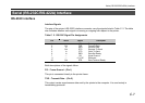
Interface Signals
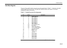
The pins of the parallel interface connector carry the signals listed in Table C. 1. Asterisks in the table
indicate signals that are active low. The table also indicates whether each signal is incoming or
outgoing with respect to the printer.
Table C. 1. Parallel Connector Pin Assignments
Pin In/out Description
1 In Strobe* [nStrobe]
2 In Data 0 [Data 1]
3 In Data 1 [Data 2]
4 In Data 2 [Data 3]
5 In Data 3 [Data 4]
6 In Data 4 [Data 5]
7 In Data 5 [Data 6]
8 In Data 6 [Data 7]
9 In Data 7 [Data 8]
10 Out Acknowledge* [nAck]
11 Out Busy [Busy]
12 Out Paper Empty [PError]
13 Out On-Line (Select) [Select]
14 In Auto-feed [nAutoFd]
15 — Not connected
16 — 0V DC
17 — Chassis GND
18 — +5 V DC
19 — Ground return
20 — Ground return
21 — Ground return
22 — Ground return
23 — Ground return
24 — Ground return
25 — Ground return
(Continued on next page)