


Serial (RS-232C/RS-422A) Interface
C-7
Serial (RS-232C/RS-422A) Interface
RS-232C interface
Interface Signals
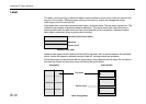
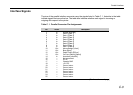
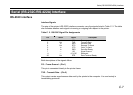
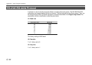
The pins of the printer’s RS-232C interface connector carry the signals listed in Table C. 2. The table
also indicates whether each signal is incoming or outgoing with respect to the printer.
Table C. 2. RS-232C Signal Pin Assignments
Pin In/out Signal Description
1 — FG Frame ground
2 Out TXD Transmit Data
3 In RXD Receive Data
4 Out RTS Request To Send
5 In CTS Clear To Send
6 In DSR Data Set Ready
7 — SG Signal Ground
11 — +5 V DC Reserved
20 Out DTR Data Terminal Ready
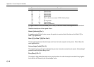
Brief descriptions of the signals follow.
FG – Frame Ground – (Pin 1)
This pin is connected directly to the printer frame.
TXD – Transmit Data – (Pin 2)
This output carries asynchronous data sent by the printer to the computer. It is used mainly in
handshaking protocols.