3. Follow the instructions that come with the drive to set jumpers or switches, if
there are any.
Note: You might find it easier to install the new drive from the front and then
attach the cables.
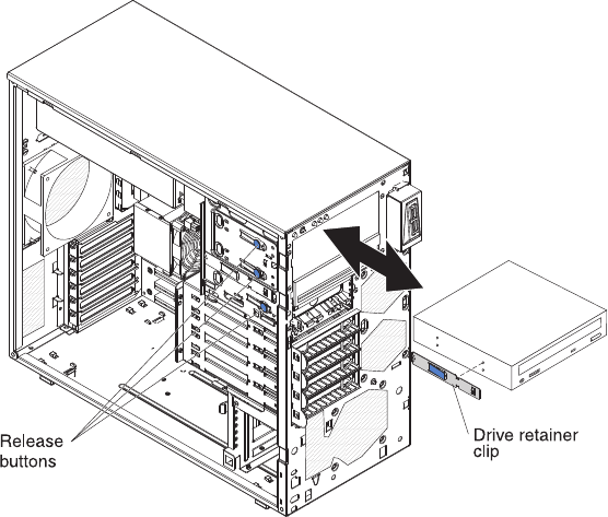
4. If you are installing a 3.5-inch drive in bay 2, attach a 5.25-inch conversion kit
to the 3.5-inch drive. Remove the drive retainer clip from the side of the drive
cage of bays 1 or 2. Slide the drive retainer clip to the right to remove it from
the drive cage; then, snap the drive retainer clip into the screw holes on the
side of the drive.
5. Push the drive into the bay.
6. Connect the power and signal cables to the drive.
Note: Route the signal cable so that it does not block the airflow to the rear of
the drives or over the microprocessor and dual inline memory modules
(DIMMs).
7. Install the upper bezel (see “Installing the upper bezel” on page 67).
8. Install the lower bezel (see “Installing the lower bezel” on page 65).
9. Install and lock the side cover (see “Installing the side cover” on page 63).
10. Reconnect the external cables and power cords; then, turn on the attached
devices and turn on the server.
Removing a tape drive
To remove a tape drive, complete the following steps:
1. Read the safety information that begins on page vii and “Installation guidelines”
on page 57.
2. Turn off the server and peripheral devices, and disconnect the power cords and
all external cables.
3. Unlock and remove the side cover (see “Installing the side cover” on page 63).
4. Remove the upper bezel (see “Installing the upper bezel” on page 67).
5. Remove the lower bezel (see “Installing the lower bezel” on page 65).
6. Disconnect the power and signal cables from the drive that is to be removed.
74 ThinkServer TS100 Types 6431, 6432, 6433, and 6434: Hardware Maintenance Manual
