


Operating the LED Display STS2
103
14.0 OPERATING THE LED DISPLAY STS2
Certain models of the STS2 do not include the LCD Color Graphical Display with the touch screen
interface. This display is replaced by an LED front panel to allow you to monitor the unit and alert
you when a problem occurs. The LED panel can be replaced with the Color Graphical Display, if
desired. Instructions for using the LCD are in 13.0 - STS2 Touch Screen Display.
You can use a PC running terminal emulation software connected to the RS-232 port to access the
data and configuration settings that are available in the Color Graphical Display touch screen.
See 12.1 - Using the RS-232 Port for instructions on setting up and using a terminal with the unit.
14.1 LEDs and Buttons and Key Lockout Switch
The LED Display unit is monitored and controlled through a series of LEDs and buttons and an
optional key lockout switch. This section includes illustrations of the LEDs, buttons and key lockout
switch, plus tables providing definitions of these components.
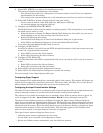
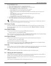
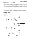
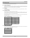
14.1.1 Front Panel Controls
The front panel contains the LEDs to monitor the STS2, plus selection buttons to choose the preferred
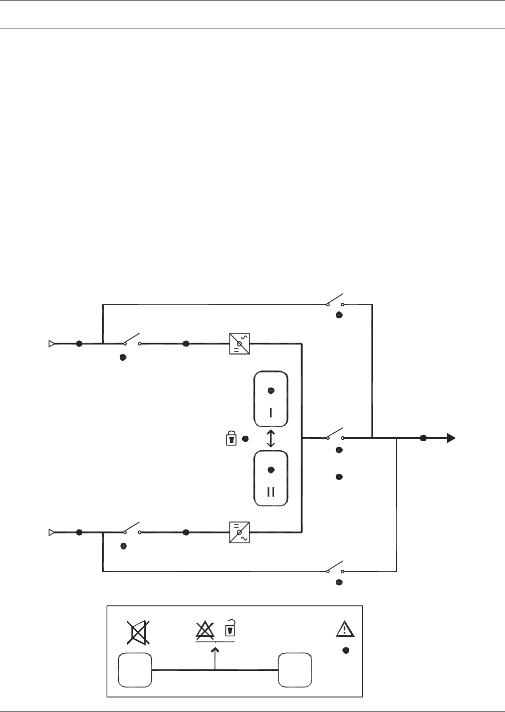
source. Figure 63 provides a breakdown of the front panel.
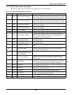
Table 16 on page 104 defines the LEDs and the push buttons on the display.
Figure 63 LED display
(F)(D)(B)
(K)
(L)
(N)(M)
5
~
2
~
(A) 1
1
(G)
~
2
(I)
3A
3
~
(C)
(E)
(H)
4
P
S
211002
Rev.
0
PS211002
Rev. 0
~
(J)