


Specifications
115
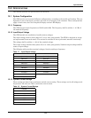
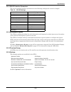
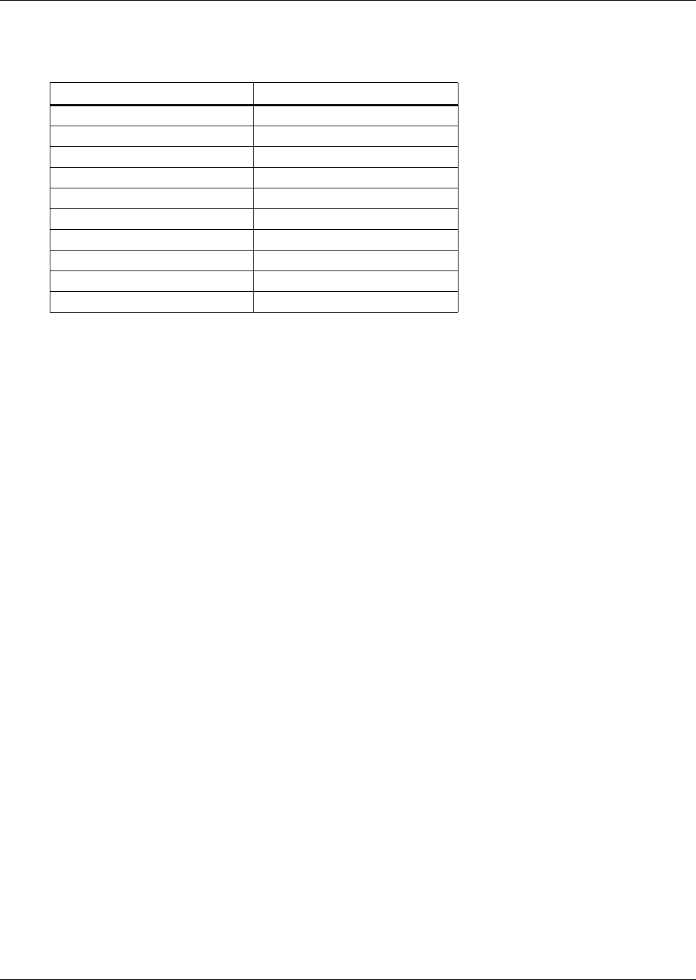
15.2.11RS-232 Interface Parameters
The service terminal interface parameters are the following settings and cannot be changed.
15.2.12Maintenance Bypass
The STS2 is configured to allow the unit’s electronics to be bypassed to either input source for mainte-
nance without interruption of power to the load.
The STS2 is furnished with key-interlocked maintenance bypass breakers to configure the bypass.
STS2 units have all electronics isolated from the input, output, and bypass connections to allow safe
servicing of any components without access to hazardous voltages when the unit is in maintenance
bypass.
See 10.4 - Maintenance Bypass on page 67 for instructions using the Color LCD Graphical Display
unit and 14.2.3 - Maintenance Bypass on page 107 for instructions using the LED units.
15.2.13Fuseless Design
All STS2 units are fuseless and are UL rated for use with upstream circuit breakers only.
15.2.14Options
The following options are available for the STS2:
See 6.0 - Options for more information.
Table 24 RS-232 Settings
Parameter Setting
Interface RS-232 Using EIA Voltage Levels
Baud Rate 9600
Parity None
Number of Data Bits 8
Number of Stop Bits 1
Hardware Flow Control Off
Terminator <CR> <LF>
Handshaking Not supported
Structure Full duplex
Local Echo Off
Optimized Transfer LED Display
Redundant Output Breaker Network Interface Card (NIC)
Distribution Cabinet With I-Line Panelboard Seismic Floor Stand - 18", 24", 30" and 36"
Input Junction Boxes and Cable Export Crating
Comms Board w/SiteScan and Modem Interface Internal Modem
Input Contact Isolator Board Remote Source Selection
Programmable Relay Board Key Lockout Switch